Note: this job there is no need to rely on any tool. If you use some tool, there is much help for your work.
ASSEMBLY
1. When installing the sharpener on a workbench, make sure that the Lock Wheel(#18).is accessible, as shown in
the mounting picture in FIGTURE 3.
2. Bolt(bolts not included) the unit directly to the workbench through the two 1/4” holes on the base(#17). The
workbench must have a solid surface capable of supporting the weight of this product the workpiece and
assorted tools. See FIGTURE 4.
Fig 3
Fig 4
Base
(
#17
)
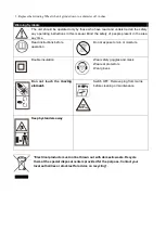
WARNING: ALWAYS UNPLUG THE UNIT BEFORE CHANGING GRINDING WHEELS, OR WHEN
MAKING ANY ADJUSTMENTS TO THE SHARPENER.
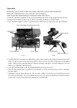
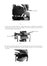
Mounting a Grinding Wheel.
Refer to the Assembly Drawing on page 10 and FIGTURE 5 and FIGTURE 6 below.
1. Raise the Top Housing(#4) and lock it in the up position by tightening the Lock Stop(#6).
2. Remove the two screws holding the Grinding Wheel Cover(#11). Set the cover aside.
3. Unscrew the screw and Grinder Lock Cap(#9) that holds the Grinding Wheel(#8) in place.
4. Install the new wheel on the Grinding Wheel Base(#7), making sure it fits properly.
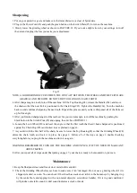
NOTE: DO NOT USE A GRINDING WHEEL IF IT IS CHIPPED, CRACKED, OR WORN. YOU CAN CHECK
IF THE WHEEL HAS CRACK NOT VISIBLE TO THE HUMAN EYE BY HANGING IT UP BY THE
CENTRAL HOLE AND TAPPING IT WITH A NON METAL OBJECT(IE: SCREWDRIVER HANDLE).
Summary of Contents for ES3000
Page 1: ......
Page 2: ...1 2 3 4 5 6 7 8 9 10 Off 11 230V 50Hz 90W 5000rpm 104mm 2 3kgs...
Page 3: ...12 On Off 13 14 15 16 0 10 50 18 AWG 17 18 1 2 7 8 3 9 4 11 5 8 6 7 8 9 10...
Page 4: ...1 1 2 2...
Page 5: ...1 18 3 2 1 4 17 4 3 4 17 10 5 6 1 4 6 2 11 3 9 8 4 7...
Page 6: ...5 9 6 11 7 6 4 8 5 6...
Page 7: ...10 4 1 2 23 31 8 3 23 7 23 23 26 18 31 7 8 4 7 8 18 18 5 4 8 6 6 9 7 26 7 26 26...
Page 8: ...6 9 8 31 34 10 34 34 10 9 10 11 Fig 11...
Page 9: ...1 2 3 5 3 12 12 4 4 34 23 34 5 5 11 6 18 23 6 7 4 8 6 6 8 7 1 2...
Page 10: ...3 3...


