background image

10

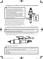
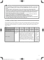
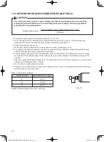
Table. 3  Overhang and Speed

Overhang (mm)

Max. Speed (min

-1

) (rpm)

20

N x 0.5

25

N x 0.3

50

N x 0.1

N=Max. Operating Speed with 13mm overhang.

Fig. 12

13

13

. CAUTIONS WHEN USING GRINDSTONES AND TOOLS

3.14 x Diameter (mm) x rotation speed (min

-

1

(rpm)

1,000 x 60

Surface Speed (m/s)  = 

CAUTION

The maximum surface speed or rpm is always specified for a grindstone. Do not exceed the 

maximum speed with reference to the calculating chart below. Always follow the grindstone 

manufacturer's recommendations.

The proper surface speed for general grindstones is 10 - 30m/s.

Do not exceed 13mm of overhang for mounted grindstones as shown in Fig. 12. If the overhang must
exceed 13mm, reduce the brushless motor speed in accordance with Table. 3.

Dress the grindstone prior to use.

Do not use cutting tools with bent or broken shanks, cracks or excessive run-out.

For grinding, the maximum depth of cut should not exceed 0.01mm radially or axially. Reciprocate the tool
several times after each pass to eliminate tool pressure.

Always operate cutting tools within the allowable recommended speed of the cutting tools. Use of a cutting 
tool outside of the allowable speed of the cutting tools could cause damage to the Spindle and injury to the 
operator.

Keep the cutting tool shank and collet clean. If contaminants are left in the collet, excessive run-out will cause 
damage to the cutting tool and or Spindle.

Do not strike or disassemble the Spindle.

Please set the cutting tools to minimize the overhang amount. 13mm is the maximum amount of overhang to 
maintain high accuracy and safety. 

OM-KK0912EN000_NR33-6000ATC-ESD_200608_下版.indd   10

2020/06/05   16:47:56

Summary of Contents for NR33-6000ATC-ESD

Page 1: ...t disconnect or touch the Power Cord Plug or Motor Cord Plug with wet hands This may cause an electric shock Never operate or handle the brushless motor and Spindle until you have thoroughly read the Operation Manuals and safe operation has been confirmed 1 To prevent injuries damages check the Spindle brushless motor and cutting tool for proper installation before operating the Spindle and brushle...

Page 2: ...cause damage to the Spindle Carefully direct coolant spray directly on the tool Do not spray directly on the Spindle body If large amount spray directly on the Spindle it may cause excess load of the Spindle rotation with loss of durability to the Spindle Stop working immediately when abnormal rotation or unusual vibration are observed Immediately please check the content of section 14 TROUBLESHOO...

Page 3: ...your safety and convenience when purchasing our products we welcome your questions If you have any questions about operation maintenance and repair of the product please contact us 3 WARRANTY We provide a limited warranty for our products We will repair or replace the products if the cause of failure is due to the following manufactures defects Please contact us or your local distributor for detai...

Page 4: ... PC boards with an end mill End Mill Size Work Thickess F Less than φ2 0mm PC board ex Glass Epoxy Resin Less than 1 6mm Less than 3 000mm min Weight 1 170g Noise Level at 1m distance Less than 70dB 6 SPECIFICATIONS AND DIMENSIONS You may need to lower feed rate mm min depending on the shape of tools being used or the thickness of work Always check the milling condition before working 6 2 Outside ...

Page 5: ...e sure your hands and all interlocking parts of the brushless motor and Spindle are clean before connecting the Spindle to the brushless motor This is critical in preventing contaminants from entering the Spindle or the brushless motor When connecting the Spindle to the brushless motor it is best to hold the brushless motor and Spindle in a vertical position Carefully connect by threading the brus...

Page 6: ...or So need the tool holder not to be damaged to the tool Replace the tool Exhaust the air through 3 way valve The collet will be closed and the tool can be fixed WARNING Do not open and close the collet while the brushless motor is running CAUTION When the air is supplied to the inlet joint of the Spindle the tool will be pushed out by exhausting the coolant air of brushless motor from the edge of ...

Page 7: ...he risk of an electric shock CAUTION When installing a Spindle do not hit drop or cause shock to the Spindle This may cause damage to internal components and result in malfunctions When installing the Spindle be sure to secure within Clamping area etched on the Spindle O D If the Spindle is installed incorrectly amage to the internal components is possible Cautions when tightening the securing bol...

Page 8: ...w for Removal Fastening Bolt Front View Side View Fastening Bolt Slit Spacer Fastening Bolt Screw for Removal Fig 11 CAUTION Do not allow set screws to come directly in contact with the Spindle body as shown in Fig 9 as this will result in damage to the Spindle housing and internal components When installing never clamp directly over the bearings as this will result in bearing damage Refer to Fig ...

Page 9: ...f the bearings The final responsibility for ensuring holder s safety for use in a given application is left to the designer of the equipment in which NAKANISHI s Spindle is installed NAKANISHI offers Spindle with a wide variety of capabilities and specifications Please carefully check the Spindle s specifications against the requirements of your equipment and verify suitability and safety of the Hold...

Page 10: ...le 3 Dress the grindstone prior to use Do not use cutting tools with bent or broken shanks cracks or excessive run out For grinding the maximum depth of cut should not exceed 0 01mm radially or axially Reciprocate the tool several times after each pass to eliminate tool pressure Always operate cutting tools within the allowable recommended speed of the cutting tools Use of a cutting tool outside o...

Page 11: ...ndles ball bearings have been damaged Tool slippage Collet is not correctly installed Check and clean the collet Reinstall the collet The collet is worn Replace the collet High run out The tool is bent Change the tool Collet is not correctly installed Secure the collet correctly The collet is worn Replace the collet Inside of the Spindle is worn Replace the Spindle shaft Return to NAKANISHI dealer...

Page 12: ...Contents are subject to change without notice 2020 06 08 005 Ⓢ OM KK0912EN000_NR33 6000ATC ESD_200608_下版 indd 12 2020 06 05 16 47 57 ...

Reviews: