background image

page

1.0 Equipment installation

Normally your Naim equipment will have been installed by the dealer who sold

it to you even if you live outside their immediate vicinity. Your dealer is

responsible for making sure that the system sounds exactly as it should and

information given here is not intended to reduce this responsibility in any way.

1.1 cables and connections

PPlease do not modify the standard interconnect cables supplied with your Naim

equipment. This is important for safety as well as performance. One end of each

cable is marked with a band to establish its correct orientation. The band always

marks the end that connects to the signal source.

Loudspeaker leads are also very important. Naim loudspeaker cable is correct for

your system and your dealer will make up leads to suit your equipment

installation. 

The leads should each be at least 3.5 metres long and of equal

length

. The recommended maximum is 20 metres. Loudspeaker leads are, like

interconnect leads, directional, and should be connected so that the printed

arrow points towards the speakers. Using alternative loudspeaker cable will

degrade performance, and may even damage your amplifier. An exception to

these loudspeaker cable constraints is the 

nap 6-50

multi-room power

amplifier. The 

nap 6-50

is designed to be tolerant of both a wide variety of cable

types, and cable runs well in excess of 20m. The loudspeaker connectors supplied

with all Naim amplifiers and loudspeakers have been specifically designed to

make a robust mechanical connection. It is essential that these are used in order

to comply with current European safety regulations.

All the plugs and sockets supplied with your Naim equipment have been chosen

because they make the best possible connection for their purpose. A poor

contact will degrade the signal substantially and plugs and sockets should look

clean and free from corrosion. The easiest way to clean them is to switch off the

equipment, pull the plugs out of their sockets, and push them back in again.

Special contact cleaners and contact enhancers should not be used as they tend

to deposit a film which is very difficult to remove and may degrade the sound.

1

1.0

Equipment Installation 
1.1 cables and

connections

2

2.0

Getting Started
2.1 switching on and off
2.2 running in
2.3 mains supply
2.4 siting the equipment
2.5 if you have a problem

3

3.0

Warnings

4

4.0

Connection
4.1 mains lead
4.2 non-rewireable mains

plugs

4.3 fuse carrier
4.4 plug fuses

5

CDS Player

10

CDX Player

14

CD5 Player

18

Narcom 2 Remote Control

20

CD Player Maintenance,
Specifications

21

EC Declaration of Conformity
to Appropriate Standards

1

Summary of Contents for CDP

Page 1: ...O W N E R S M A N U A L C D P l a y e r s...

Page 2: ...is the nap 6 50 multi room power amplifier Thenap 6 50 is designed to be tolerant of both a wide variety of cable types and cable runs well in excess of 20m The loudspeaker connectors supplied with a...

Page 3: ...e a lower impedance supply cleaner power and consequently improve system performance Do not wire voltage dependent resistors or noise suppressors into mains plugs They degrade the mains supply and the...

Page 4: ...g an overall improvement in sound quality It may be necessary however to take account of mechanical transformer noise when siting your equipment In some circumstances depending on where you live and t...

Page 5: ...t Do not use the plug until the fuse carrier is replaced 4 4 plug fuses Replace only with ASTA or BS 1362 approved fuses 4 note This equipment has been tested and found to comply with the relevant EMC...

Page 6: ...the previous or next functions to select a different track To play the chosen track you will then need to undo the pause with a second press of the button stop Stops the disc rotating returns the lase...

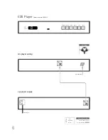
Page 7: ...play track time repeat program mains input CDS Player from serial no 146541 xps power supply cable direction marker 5 to 5 pin DIN 11 to 11 pin Burndy ch1 nc nc ve ch2 CDS output Interconnect Cables...

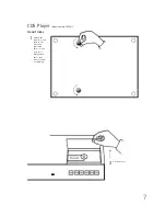
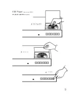
Page 8: ...7 CDS Player from serial no 146541 transit locks 1 Open the door Unlock the transit screws fully in the direction indicated Remove and keep safe Always lock these last before transit or shipping 2...

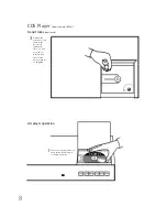
Page 9: ...ke sure it is seated properly cds player operation CDS Player from serial no 146541 transit locks continued Unlock the transit screws fully in the direction indicated Remove and keep safe Always lock...

Page 10: ...9 2 3 4 Place the disc clamp on the compact disc CDS Player from serial no 146541 cds player operation continued Close the door Press play...

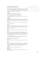
Page 11: ...o play beginning with track one unless another track has been selected If you press play while a track is already playing the track will be re started When an HDCD encoded compact disc is loaded the C...

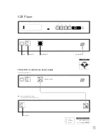
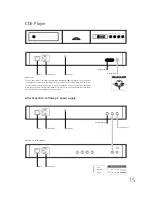
Page 12: ...for improved performance mains input CDX Player cable direction marker 5 to 5 pin DIN 11 to 11 pin Burndy to preamplifier mains input power link plug fitted link plug removed ch1 nc nc ve ch2 CDX out...

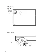
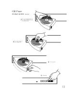
Page 13: ...12 CDX Player transit lock 1 Remove the transit screw keep safe Always replace this before transit or shipping Open the door 1 cdx player operation...

Page 14: ...CDX Player cdx player operation continued 2 3 4 5 Place the compact disc on the platter Make sure it is seated properly Place the clamp on the compact disc Close the door Press play 13...

Page 15: ...oad condition play play Causes the player to enter play condition The loaded disc will start to play beginning with track one unless another track has been selected If you press play while a track is...

Page 16: ...t stop play flatcap 2 power supply signal out D please note The RC5 input fitted to cd5 players manufactured after March 2001 is designed to accept external control signals for multi room applications...

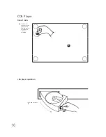
Page 17: ...16 CD5 Player transit locks 1 Remove the transit screws keep safe Always replace this before transit or shipping Open the door 1 cd5 player operation...

Page 18: ...2 3 4 5 Place the compact disc on the platter Make sure it is seated properly Place the clamp on the compact disc Close the door Press play 17 CD5 Player cd5 player operation continued...

Page 19: ...ard while recording in order to check the off tape signal The source to be recorded is chosen by the input selector buttons in the normal way After pressing mon select the input to which your machine...

Page 20: ...age may result if the unity gain feature is used inappropriately To return to the default settings press and hold the prog key until the amplifier volume control indicator flashes Press and hold disp...

Page 21: ...erred to main response Distortion Noise 0 1 10Hz 18kHz at full level Laser Type Semiconductor AlGaAs Wavelength 780nm Mains Supply 100V 115V 230V 50 or 60Hz Case Size H x W x D 58 4 x 432 x 301 mm CD...

Page 22: ...S6 EN 60 065 EMC Emissions Tested to EN 55013 Sound and television broadcast receivers and associated equiment Immunity Tested to EN55020 Electromagnetic immunity of broadcast receivers and associate...

Reviews: