Nailor Industries Inc. reserves the right to change any information concerning product or specification without notice or obligation.
Page 2.094
3/16 IOM-MBFDIMP
OPERATION AND MAINTENANCE PROCEDURES
MULTI-BLADE AND TRUE ROUND FIRE DAMPERS
MODEL SERIES: (D)1200(SS)(-3)(-OW)(-DOW), D1250
AND 1290F(-SS)
Dampers are an essential part of the fire protection system
in a building. The NFPA recommends that fire dampers be
tested periodically to verify the operational abilities of each
installed damper. See NFPA 80,
Standard for Fire Doors
and Other Opening Protectives
, for Operational and
Periodic Inspection and Testing details.
CAUTION:
High torque helical spring under tension, ensure HVAC
fans are turned off. Testing spring assisted fire dampers
under airflow conditions is
NOT RECOMMENDED
and
may severely damage or destroy ductwork. Use protective
eyewear or safety glasses. Keep hands out of the blade
path, as this can cause serious injury. Keep any hard
objects or tools out of the blade path as they can damage
the blades when closing.
Releasing of the fusible link
1. Using a suitable heat source, apply heat at a slightly
higher temperature than the rating of the fusible link until
the link melts. When applying the heat to the fusible link
position the heat source in a manner so no heat is directed
towards the spring as the excessive heat can negatively
affect the spring performance.
AS SOON AS THE LINK HAS MELTED, THE
SPRING WILL FORCE THE BLADES TO CLOSE
INSTANTANEOUSLY. THE BLADE PATH MUST BE
KEPT CLEAR.
Reloading the spring assembly
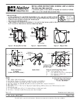
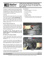
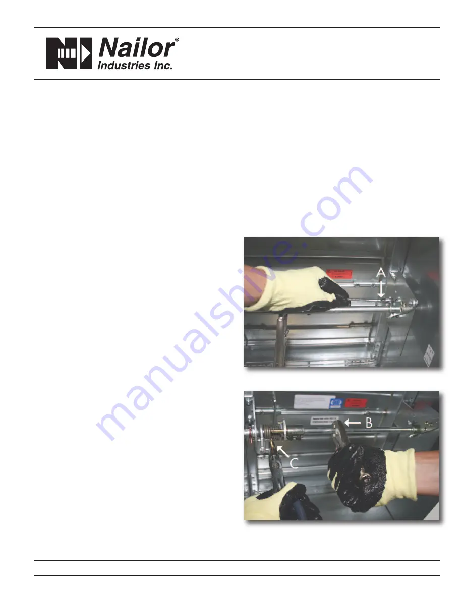
2. Loosen the jackshaft from the bolt on crank arm
quadrant, located on the jackshaft side opposite of the
spring assembly
(A)
. Do not remove the bolt completely.
See Detail 1.
3. Attach a pair of vise grips on the jackshaft
(B)
and turn
upwards until the two pins on the spring assembly are at a
distance at which the new fusible link can be installed
(C)
.
This is approximately 90° of rotation. See Detail 2.
Note:
On smaller size dampers, two vise grips may be
required to open the damper. Use one vice grip to open as
much as the duct free area will allow, then set the second
vise grips on the jackshaft per above. Unlock the first set of
vise grips, remove and turn the second set upwards as
free area will allow. Repeat as necessary.
4. Place the new fusible link over the two pins on the
spring assembly (making sure temperature rating is visible)
and locate in the pin grooves
(C)
. See Detail 2.
Required Items:
(1) Protective eyewear or safety glasses
(1) Pair of work gloves
(1) Suitable heat source
(2) Vise grips
(1) 1/2" (13) wrench
(1) Needle nose pliers
(1) Replacement "Globe" Fusible link per damper section,
of the same temperature rating as the original link.
Detail 1
Detail 2
Page 1 of 2


