Page
" C o m p l e t e A i r C o n t r o l a n d D i s t r i b u t i o n S o l u t i o n s . "
w w w . n a i l o r . c o m
Calgary, Canada
Tel: 403-279-8619
Fax: 403-279-5035
Houston, Texas
Tel: 281-590-1172
Fax: 281-590-3086
Toronto, Canada
Tel: 416-744-3300
Fax: 416-744-3360
Las Vegas, Nevada
Tel: 702-648-5400
Fax: 702-638-0400
Page 2.081
11/09 IOM-1290FINST
GENERAL INSTALLATION:
1.
Installation shall be in accordance with NFPA 90A, latest edition. Connecting duct gauge shall be 20 gauge (1.0) maximum (standard integral damper sleeve) and in
accordance with SMACNA Duct Construction Standards. (Exception, see Note 7).
2.
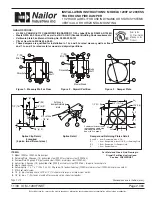
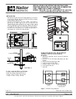
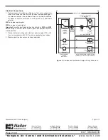
The square (drywall/masonry) or round (masonry) wall opening shall be 1" (25) larger than the overall size of the damper diameter.
3.
If not supplied, fabricate retaining plate and damper plate using dimensions shown in details.
4.
Install retaining plate in groove on actuator side of damper using 1/4" (6) dia. nut and bolt through splice clip. Install damper within wall opening as shown in Figure
1 or 2. Install damper plate and clamp using 1/4" (6) dia. nut and bolt through splice clip. Both retaining and damper plates should be tight to the wall.
5.
On drywall installations screw the retaining and damper plates to the wall through the 3/16" (5) dia. holes in the corners of the plates. Major diameter or body of screws
must engage metal or wood studs or runners. On masonry installations, the damper plate shown in Fig. 3 should be used. This has four equally spaced clips 1" x 1" x 1"
(25 x 25 x 25) 20 gauge (1.0) which are attached to the plate and damper sleeve using 3/16" (5) rivets, tack or spotwelds. (Make sure that fasteners do not interfere
with the operation of the damper blade). For dampers 12'' (305) dia. or less, single side retaining plate may be used (damper plate optional) but retaining plate must
be fastened to wall or floor with 6 screws instead of 4.
6.
The connecting duct shall not be continuous through the wall or floor but shall terminate at each end of the damper sleeve. Sleeves shall extend a maximum of 6" (152)
on either side of the wall or floor opening or 16" (406) on one side intended for use with an actuator or an access door. The sleeve may extend a maximum of 16" (406)
on each side when access door and actuator are on opposite sides.
7.
Connecting ducts shall be attached using three equally spaced #10 sheet metal screws or a 4" (102) wide draw band spanning the joint Duct sealant may be used.
If damper frame/sleeve and connecting duct are 16 gauge (1.61), a rigid duct connection may be used.
8. Maximum Damper Size:
24" (610) dia. Minumum size is 6" (152) dia.
Page 2 of 2
Dimensions are in inches (mm).
REFER TO THE APPROPRIATE NAILOR INSTALLATION INSTRUCTION
SUPPLEMENTS FOR ADDITIONAL INFORMATION OR SPECIAL
REQUIREMENTS:
MLS-300 (Nailor) POSITION INDICATOR
MLS3N
STEEL AND WOOD STUD FRAMING
FDSWSFINST
CAVITY SHAFT WALL PARTITIONS
FDCSWINST


