background image

14

3.1.8 Scoreboard

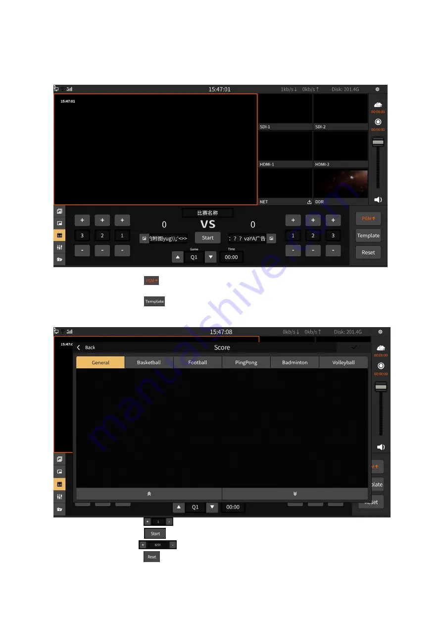
The scoreboard can record the score of the live match in real time as shown in the figure below:

1) Button operation is as follows:

Button

: Display the score board to the PGM channel and click again to cancel

the display.

Button

: Choose the template of the scoreboard. The templates are general,

basketball, football, table tennis, badminton and volleyball. It also support online

download. In order to download, just click the “Download” button as shown below:

Button

: “+/-” can “increase/decrease” scores in real time.

Button

: Start/pause timing. The status will become yellow highlight when it

start.

“+/-” can “increase/decrease 1 second” in real time.

Button

: Clear the score and timing.

Summary of Contents for NSCaster X1

Page 1: ...NSCaster X1 User Guide REV 599 Copyright 2006 2018 NANJING NAGASOFT CORPORATION All rights reserved ...

Page 2: ...S 8 3 1 NSCASTER X1 MAIN INTERFACE 8 3 1 1 PGM 8 3 1 2 SDI Channel 9 3 1 3 HDMI Channel 9 3 1 4 NET Channel 10 3 1 5 DDR Channel 10 3 1 6 Image Overlay 11 3 1 7 PIP Picture in Picture 13 3 1 8 Scoreboard 14 3 1 9 Audio Mixer 15 3 2 NSCASTER X1 SETTINGS INTERFACE 16 3 2 1 Channel Recording 16 3 2 2 Recording 17 3 2 3 Streaming 18 3 2 4 Clock 20 3 2 5 Network 21 3 2 6 File Transfer 22 3 2 7 General ...

Page 3: ... no condensation Impact resistance 15g Vibration resistance 10 100Hz 1 25g Altitude Below 4000 meters Name Model Package Specification Number of Pieces Actual Quantity Remarks Main device Carton packaging NSCasterX1 1 1 Power supply and power cord Carton packaging Standard 1 1 WIFI antenna Carton packaging Standard 1 1 4G antenna Carton packaging Standard 2 2 Standard Version 4G antenna Carton pac...

Page 4: ...face of the standard version is shown below 1 4G antenna 7 USB3 0 13 HDMI Display interface 2 4G antenna 8 Gigabit Ethernet port 14 HDMI PGM Output 3 WIFI antenna 9 SDI 1 Input 15 SDI PGM Output 4 Switch 10 SDI 2 Input 16 TALLY 5 Power supply DC 19V 11 HDMI 1 Input 17 Cooling port 6 USB2 0 12 HDMI 2 Input 17 ...

Page 5: ...B3 0 18 HDMI PGM Output 5 SIM1 card holder 12 Gigabit Ethernet port 19 SDI PGM Output 6 SIM2 card holder 13 SDI 1 Input 20 TALLY 7 SIM3 card holder 14 SDI 2 Input 21 Cooling port 1 4 2 Side Interface The side interface for both standard version and 4G bonding version are the same as shown below 1 XLR TRS balanced input L 4 XLR TRS balanced output L 2 XLR TRS balanced input R 5 XLR TRS balanced out...

Page 6: ...4 1 4 3 Bottom interface 1 The bottom interface of the standard version is shown below 1 SIM card holder 2 Inlet 2 The bottom interface of the 4G bonding version is shown below 1 Inlet ...

Page 7: ... the SDI HDMI input via SDI HDMI cable as shown below The mixer is connected to the TRS MIC input port through the TRS cable or the XLR cable is connected to the XLR input as shown below 4 In order to connect the NSCaster X1 device output port to the monitor it has divided into following categories The SDI monitor is connected to the SDI output via an SDI cable The HDMI monitor is connected to the...

Page 8: ...m audio cable as shown below 6 To start the NSCaster X1 device just press the power button on the NSCaster X1 device as shown below 7 After the NSCaster X1 device is started it will enter the main interface of NSCaster X1 as shown in the following figure ...

Page 9: ...o start record 12 To start switching tap once on the channel you want SDI 1 SDI 2 HDMI 1 HDMI 2 NET DDR and it will switch to PGM 13 Start uploading the picture on PGM as shown below 14 Press again the record button to stop recording 15 Check whether all the recording files are normal The recording file is saved in the Recording folder which located at the File Transfer interface 16 Press the Powe...

Page 10: ...al mix output 4 NET input channel 12 Image overlay 5 DDR display channel 13 PIP Picture in picture 6 Network status display 14 Scoreboard 7 Resource usage monitoring status 15 Audio mixer 8 Settings button 16 DDR 3 1 1 PGM PGM channel Monitor the screen that being broadcast Single tap on the channel you want SDI 1 SDI 2 HDMI 1 HDMI 2 NET DDR and it will switch to PGM as shown below ...

Page 11: ...9 3 1 2 SDI Channel SDI 1 and SDI 2 can be connected to SDI cameras or other devices as shown below 3 1 3 HDMI Channel HDMI 1 and HDMI 2 can be connected to HDMI cameras or other devices as shown below ...

Page 12: ...ET channel is used to load network streams and the supported formats are rtmp rtsp Click to enter the network stream editing interface as shown below 3 1 5 DDR Channel The DDR channel is used to load video footage as shown below ...

Page 13: ...ged to adjust the video progress 3 1 6 Image Overlay Image overlay panel can publish image to the PGM monitor It support png image format and location movement of images as shown below 1 Click the button to enter the photo editing interface and then click the button to add a picture There are two ways to source images Online download Click Download to download Customize My Picture You can copy the...

Page 14: ...r the photo editing interface as shown below Button operation is as follows Four button Adjust the position of the picture in the up down left and right directions Button Zoom in Button Zoom out Button Restore image to initial state 4 Select the image and click to delete the image ...

Page 15: ...nd the A area of the PGM will display the screen of SDI 1 channel The channel screen of A B C D area on the PGM channel supports real time switching The picture in picture template is divided into the following two types 1 No background image template as shown below 2 Add background image template The background image is stored in the Picture Clips folder which located at the File Transfer interfa...

Page 16: ...y Button Choose the template of the scoreboard The templates are general basketball football table tennis badminton and volleyball It also support online download In order to download just click the Download button as shown below Button can increase decrease scores in real time Button Start pause timing The status will become yellow highlight when it start can increase decrease 1 second in real ti...

Page 17: ...3 1 9 Audio Mixer The mixer is used to control the gain and mix of all input and output audio as shown below 1 Button operation is as follow Button Mixing output Button Mute Button Volume adjustment fader ...

Page 18: ... below 3 2 1 Channel Recording It can record channel audio and video and also support recording of SDI 1 SDI 2 HDMI 1 HDMI 2 and NET channels The recorded files are stored in the Record channel folder which located at the File Transfer interface The bitrate and GOP in the interface can be customized Click the custom box to pop up the editing interface where the bitrate custom interface as shown be...

Page 19: ...cording and click again to stop The recorded files are stored in the Record pgm folder which located at the File Transfer interface as shown below The bitrate and GOP in the interface can be customized Click the custom box to pop up the editing interface where the GOP is customized as shown below ...

Page 20: ...e to start the streaming and click again to stop Video bitrate and GOP can be customized as shown below 1 Select the server type as RTMP and if channel push protection is set then it require user to enter the username and password If not just ignore it The format of rtmp is ip port live and stream name is the name of the channel as shown below ...

Page 21: ... Mudu live platform then fill in the username and click on the authorization to get the channel and encoding information as shown below 3 Select the server type as AndLive First you need to enter the username and password then log in to get the activity list as shown below ...

Page 22: ...ization first as shown in the figure below 3 2 4 Clock Clock configuration status will let user know whether is on off based on the status If the status is ON means the clock is on right now and if the status is OFF means that the clock is off After being turned on the current time can be displayed on the PGM monitor and the format and the position of the clock support real time switching as shown...

Page 23: ...hat it is connected 1 Ethernet The default boot and the access network cable will automatically obtain the IP Open DHCP and click Apply to get the IP address automatically or turn off DHCP to manually modify the IP address as shown below 2 WIFI Select the WIFI you want to connect and enter the correct password Click the button to scroll up and down ...

Page 24: ...ffect the switch of the 4G bonding device The 4G bonding device will automatically start the 4G network when it is inserted into the SIM card and the 4G signal will be disconnected when the SIM card is pulled out 3 2 6 File Transfer File transfer between local files and USB flash drives as shown below ...

Page 25: ...s follows Button Return to the main interface directory of the file Button Return to the previous directory Button Delete files Button Refresh Button Choose a different USB flash drive different partitions of the same USB flash drive Button Slide up and down Button Copy locally to a USB flash drive Button Copy from USB flash drive to local Button During file copying cancel the copy by the cancel b...

Page 26: ... switching the system you need to click the Apply button to restart the software automatically as shown below 2 Language It support real time switching language Simplified Chinese Traditional Chinese English 3 Brightness Adjust the brightness of the screen according to the actual scene 4 Mouse ON status means that mouse is operable OFF status means that mouse is not operable ...

Page 27: ...update and firmware update when there is available as shown below 1 The button operation is as follows Software Update It will pop up update interface and update instructions Download the update Download the latest version Cancel download Cancel the currently downloaded version Restart Install the download version and restart the software ...

Page 28: ...on to test and make sure that the device is properly connected After that check the upload and download speed whether is normal or not Then confirm whether the server address port and publishing point flow name are correct Q3 What can I do if WIFI cannot connect Ans First check if the WIFI antenna is connected properly then check if the 4G antenna is misused After that check if the WIFI is enabled...

Reviews: