


14
Installation and operation manual
–
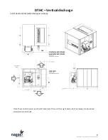
DTHC-V4-2020
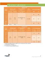
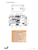
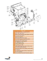
Depending on the model, the flue vent connector diameter ranges from 6 to 8 inch. The DTHC model
series is designed to operate effectively and safely (against a positive pressure of 0.35 in.w.c) with a
positive stack (category IV) type
sealed single wall or double wall flue vent
listed
for this application,
whether vertical arrangement or horizontal or a combination of both. The minimum diameter of all
sections must be identical to the unit’s connection diameter
or greater.
Do not intermix different
listed vent system parts from different manufacturers in the same venting system.
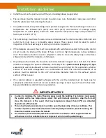
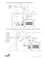
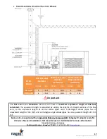
A listed vent cap or termination of the same diameter as the exhaust pipe must be used at the
extremity located at the exterior of the building. See pictures below for recommended end cap and
configurations. The exhaust pipe must end at the exterior of the building while respecting (at least
but not limited to) the following clearances:
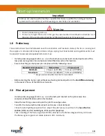
Clearances for vent terminals **
Structure
Minimum Vent Terminal Clearances***
Motorised air intake less than 1.8m
(6’)
0.9m (3’) above and 1.8m (6’) to the side
Combustion air intake from another device
1.8m (6’) above and 1.8m (6’) to the side
Door, openable window, revolving door or
all other openings
1.8m (6’) to the side
0.9m (3’) above
Electrical or gas meter, regulator and relief
equipment *
1.8m (6’) to the side (Canadian standards)
1.2m (4’) to the side (U.S.A. standards)
Vent outlet from another service
0.9m (3’)
Building or adjacent wall or parapet
1.8m (6’)
(might have to be increased for horizontal
discharge)
Sidewalk or parking lot
2.1m (7’) above
Ground vent
0.3m (1’) above snow level
Wall of vent outlet
0.3m (1’) minimum
Roof of vent outlet
0.9m (3’) minimum and 0.6m (2’) above all obstacles
less than 3m (10’)
*
Never install a flue vent outlet above a service regulator or a gas meter.
** Local codes always supersede the above provisions.
*** Take all necessary precautions to avoid the installation of vent outlets where snow accumulation
can occur naturally or due to roof snow slides or snow removal dumps. In the case of a horizontal
exhaust, a secure distance of 3m (10’) must be added to the distance found in the table for horizontal
direction, measured from the mechanical or gravity air intakes.
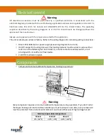
The flue vent must be built using a category IV listed vent pipe system sealed corrosion resistant steel
pipe having a minimum thickness of 24 gauge or heavier, in the interior of the building. However a
double-wall corrosion resistant pipe section is required to get through the external walls of the
building to the vent cap (consult vent pipe supplier instructions).
The flue vent joints must be sealed in a manner that will not allow leakage of the combustion product
into the room. See flue vent manufacturer instructions for more details.
Flue vent and combustion air


