9
RF PATTERN TESTING
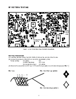
Testing Point
R132
Testing
Point
J334
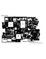
NAD - C 541 PCB TESTING POINTS DIAGRAM
TESTING PROCEDURE
(1) Load the test disc (Sony Test CD YEDS-7) and set the unit into PLAY mode.
(2) Connect the scope to R132 (Pin 41 of U101) and DGND (J334).
Scope setting:
Coupling
: AC.
Vertical sensitivity
: 0.2 V/ div.
Horizontal time base
: 0.5 µS/div.
(3) Observe the waveform is 2.0V p-p +/-5% and the eye pattern is at its best shape (see FIG. 1).
FIG. 1 (a)
FIG. 1 (b) Poor eye pattern
FIG. 1 (C) Good eye pattern
3T 4T 5T — 11T
Summary of Contents for C541
Page 1: ...NAD SERVICE MANUAL C 541 COMPACT DISC PLAYER C 541COMPACT DISC PLAYER ...
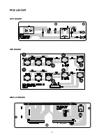
Page 12: ...12 PCB LAYOUT LIVE BOARD KEY BOARD DISPLAY BOARD ...
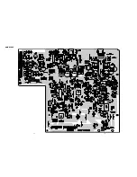
Page 13: ...14 13 MAIN BOARD ...
Page 25: ...27 MECHANISM EXPLODED VIEW CD11CA ...
Page 27: ...29 EXPLODED VIEW OF LASER CD11CA G ...
Page 32: ...SERVICE MANUAL NAD 2001 C 541 COMPACT DISC PLAYER NAD ELECTRONICS INTERNATIONAL TORONTO ...


