background image


Page-8 


5.  Installation procedure 

The installation location and the installation procedure of the robot are critical factors to maintain robot 
functions. The ambient conditions of installation location not only have influence on the life of mechanical 
sections of the robot, but also get involved in safety issues. Consequently, strictly observe the 
environmental conditions shown below. Furthermore, utmost care should be exerted for the installation 
procedure and the foundation for the robot in order to maintain the robot performance. Strictly observe 
the installation procedure for the robot provided below. 


Installation


To install the robot, give it first priority to thoroughly consider safety of workers and take safety 
measures. The following describes precautions for this purpose. 


Safety measures against entry in the robot operating area


WARNING 


While the robot is in operation, workers are in danger of coming in contact with the 

robot. To avoid that, install a 

guard fence

 so as to keep the worker away from the robot. 

Not doing so will cause the workers or other persons to accidentally enter the operating 
area, thus resulting in accidents. 


■ 

Space surrounding robot
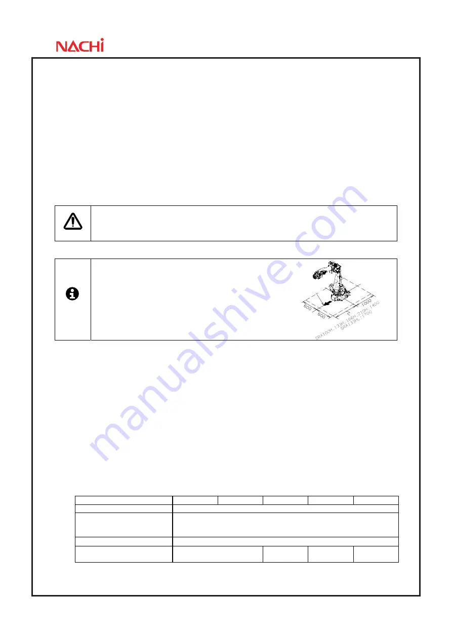
 

IMPORTANT


When installing this robot, open space written 

in figure is necessary for maintenance work such 
as motor replacement, balancer replacement and 
other work. 


■ 

Installation location and ambient conditions


Conditions (temperature, humidity, height and vibration) are written in “2. Basic Specifications”. 
Further ambient conditions listed below must be observed. 
(1) Location with the drainage structure so that swivel base is not flooded, when the liquid such 

as water or cutting fluid is splashed on the robot body 

(2) Location with no flammable or corrosive fluid or gas. 
(3) Type D grounding (the grounding resistance is 100

Ω

 or less) is necessary. 


■ 

Installation procedure


While robot moves, large reaction force is applied to the swiveling base from all directions. 
Consequently, the robot should be installed in such a manner that the foundation endures not 
only the static loads but also the reaction force caused by robot movement. 
Repair uneven spots, cracks, and others on the floor, and then install the robot by following to 
the table below. If thickness of floor concrete is less than needed level, an independent 
foundation should be constructed. Inspect the foundation prior to the robot installation, and then 
construct the foundation, if necessary. 


Robot Model 

SRA100H-01 SRA133H-01 SRA166H-01 SRA210H-01 

SRA133HL-01

Thickness of floor concrete 

Not less than 160 mm 

Installation parts *1 

8 bolts of M20 (JIS: Strength class 12.9) not less than 65mm 
8 plain washers of not less than 4.5 mm in thickness 

and HRC35 in hardness 

Tightening torque *2 

560 

±

 30 N

Allowable repeated tensile *3 

Approx. 

22,000 N 

Approx. 

28,000 N 

Approx. 

30,000 N   

Approx. 

28,000 N 

*1 : Installation parts are not accessory of robot. 
*2 : Apply a coating of lubricating oil to the threaded parts of bolts, and then tighten bolts by using torque wrench to the 

specified tightening torque. 

*3 : This tensile is per installation bolt when robot is installed with all bolts written in table above. 

Axis1 = 0 degree

Summary of Contents for SRA-H Series

Page 1: ...Standard specifications SRA H 01 FD11 SRA HL 01 FD11 6th edition 1608 SSRAEN 071 006 001 ...

Page 2: ...oad mounting plate 6 5 Installation procedure 8 6 Allowable wrist load 11 7 Option specifications 18 8 Application wiring and piping diagram 21 9 Safety measures against transport 24 10 Delivery style specification which contains a robot 26 11 Consuming power Robot Controller 26 12 Paint color 26 13 Warranty 26 ...

Page 3: ... high rigidity and quick motion control resulting in high acceleration and minimum vibration Ease of use Operating range of robot is irrelevant to the payload mass Axis 5 wrist operating range is maximum in its class These features open the robot to more diverse applications thus resulting in easier application design 1 By installing the balance unit inside arm swivel base becomes slim Slim and co...

Page 4: ... 441 N m Axis 4 85 kg m 2 100 kg m 2 200 kg m 2 85 kg m 2 Axis 5 85 kg m 2 100 kg m 2 200 kg m 2 85 kg m 2 Allowable moment of inertia 2 Axis 6 45 kg m2 50 kg m 2 155 kg m 2 45 kg m 2 Position repeatability 3 0 1 mm 0 15 mm Installation Floor mount Ambient conditions Temperature 0 to 45 ºC 4 Humidity 20 to 85 RH No dew condensation allowed Vibration to the installation face Not more than 0 5G 4 9 ...

Page 5: ...Page 3 3 Robot dimensions and working envelope SRA100H 01 SRA133H 01 ...

Page 6: ...Page 4 SRA166H 01 SRA210H 01 ...

Page 7: ...Page 5 SRA133HL 01 ...

Page 8: ...bes are pulled out from the center portion of end effecter So please make a hole of φ100 on end effecter for easier maintenance without dismounting it If making hole on end effecter is impossible extension flange option is prepared in order to pull out cables from the side SRA100H 01 SRA133L 01 SRA133HL 01 SRA166H 01 SRA210H 01 IMPORTANT Be sure to use P C D 160 tap hole when tool weight is more t...

Page 9: ...pper part of forearm Ancillary equipment can be mounted to the upper part of robot forearm SRA100H 01 SRA133H 01 SRA166H 01 SRA210H 01 SRA133HL 01 Cross section view of Z Z 4 portions Gear box Bracket Tap depth ...

Page 10: ...ications Further ambient conditions listed below must be observed 1 Location with the drainage structure so that swivel base is not flooded when the liquid such as water or cutting fluid is splashed on the robot body 2 Location with no flammable or corrosive fluid or gas 3 Type D grounding the grounding resistance is 100Ω or less is necessary Installation procedure While robot moves large reaction...

Page 11: ...e robot working envelope can be regulated for safety optional function Since optional parts should be installed to enable this function do not independently move the standard parts e g mechanical stopper WARNING If mechanical stopper collides and robot stops it s possible that some parts are already damaged for example mechanical stopper is transformed or fixing bolts are broken In this case suffi...

Page 12: ...when you weld with the base plate installed in the robot body by the welding spatter and the spark etc so that wiring in the robot should not receive damage After welding the outer line once remove the robot and weld the inner line Temporary install the robot and weld the outer line of base plate Protection necessary for 4 positions front rear right and left Four Base plates Weld the outer line of...

Page 13: ...ment of inertia Strictly keep the wrist load within each allowable value If wrist load exceeds the allowable value this robot is out of guarantee Refer to the table of 2 Basic specifications and following figures for the detail of each specification Torque map C O G of wrist load should exist inside the range shown below SRA100H 01 SRA133H 01 SRA133HL 01 ...

Page 14: ...Page 12 SRA166H 01 SRA210H 01 ...

Page 15: ... of inertia of wrist load should exist inside the range shown below IMPORTANT If the real inertia is over the limit written in 2 Basic specifications maximum speed will be restrained by software SRA100H 01 SRA133H 01 SRA133HL 01 Axis 4 5 Axis 6 Axis 4 5 Axis 6 ...

Page 16: ...Page 14 SRA166H 01 SRA210H 01 Axis 4 5 Axis 6 Axis 4 5 Axis 6 ...

Page 17: ...COG coordinate system xyz If tool is regarded as prism it is calculated as right formula 12 1 12 1 12 1 2 2 2 2 2 2 C B m I C A m I B A m I z y x lx A B C If tool is regarded as prism ly lz m Inertia moment example on tool COG coordinate system 2 Calculate inertia moment on wrist coordinate system XYZ If tool is regarded as aggregate of more than one solid all inertia moment must be combined z m m...

Page 18: ...ot under condition that COG of the ancillary equipment on the forearm falls in the range shown below SRA100H 01 When wrist load is 100kg SRA133H 01 When wrist load is 133kg SRA166H 01 When wrist load is 166kg SRA210H 01 When wrist load is 210kg ...

Page 19: ...Page 17 SRA133HL 01 When wrist load is 133kg ...

Page 20: ...13 10 Extension flange Flange to pull out cable from side P C D 92 P C D125 and P C D160 Pin arrangement horizontal OP W3 014 11 Scale seal For wrist three axes OP N2 020 For 100 133kg payload OP N5 036 For 166kg payload OP N5 049 For 210kg payload OP N5 047 12 Water proof coolant Paint For 133kg Long arm type OP N5 037 13 Encoder connector Protector For axis 3 OP P6 005 Bypass of motor and encode...

Page 21: ...pcs set Axis 2 Adjustable LS Axis 3 Axis 1 Axis 2 Dual circuit Limit Switch Adjustable stopper and Adjustable LS Axis 3 1 These parts are packed separately from the robot Not attached on the robot 2 In this option both axis 1 adjustable stopper and axis 1 adjustable LS dog part are supplied in 1 package Please be sure that even if only the stopper part is used and no LS is used the dog part is als...

Page 22: ...C D 160 Two type is prepared for attachment phase of P C D 92 P C D 125 Attachment phase of P C D 160 is same for both flanges Pin arrangement is direction of P C D 92 P C D 125 pins when axis 6 is in 0 degree Tool mounting face of OP W3 013 Pin arrangement is vertical Tool mounting face of OP W3 014 Pin arrangement is horizontal ...

Page 23: ...iring and piping written here is the best designed specification for spot welding usage No free space is remained in hollow space If another specification is required please contact to NACHI FUJIKOSHI office Spot welding specification Connecting diagram Standard ...

Page 24: ...11 5 Connector type MS3106A20 17S D190 Cable Servo gun cable signal x1 9 Connector type MS3106A20 29S D190 1 Spot welding specification Utility Water inlet tube Green 1 2 φ12 φ8 2 Water outlet tube Red 1 2 φ12 φ8 2 Air tube White 1 3 φ12 φ8 1 Manufacturer Chiyoda engineering Cut tube type TE 12 AF Recommended joint one touch joint for φ12 1 1 Joint is not included 2 Water pressure is 0 2MPa or low...

Page 25: ...is drawn seeing from the backside of the robot Application wiring specification Rated voltage Max AC DC 115 V Rated current rating Max 1 A BJ3 side connector option Connector form CN61 CN63 Housing SMP 10V BC JST User side Connectors Housing SMR 10V B JST Contact SYM 001T P0 6 applicable wire AWG 22 28 Manual crimp tool YRS 121 Connector form CN62 CN64 Housing SMP 11V BC JST User side Connectors H...

Page 26: ...rmore after installing the robot take protective measures such as using protective guards so that the wirings will not be damaged by workers or other persons or forklift trucks or else WARNING Gas in balancer must be released when robot is transported by air Gas in balancer must be charged before using robot so customer needs to prepare the nitrogen gas and charging unit Charging procedure is writ...

Page 27: ... If hanging wires push the encoder connectors or wiring piping they may be broken when hanging the robot When hanging the robot please pay attention not to make the wires touch the encoder connectors and wiring piping ...

Page 28: ... must be charged before using robot so customer needs to prepare the nitrogen gas and charging unit Please contact to NACHI FUJIKOSHI office to order the charging unit Charging procedure is written in manipulator maintenance manual 2 Operation and maintenance education The special spot operation guide and the special spot preservation guide are the outside of the estimation Consult with each NACHI...

Page 29: ......

Page 30: ... Istanbul TURKEY NACHI AUSTRALIA PTY LTD http www nachi com au Robotic Division Victoria office Phone 61 0 3 9796 4144 Fax 61 0 3 9796 3899 38 Melverton Drive Hallam Victoria 3803 AUSTRALIA Sydney office Phone 61 0 2 9898 1511 Fax 61 0 2 9898 1678 Unit 1 23 29 South Street Rydalmere N S W 2116 AUSTRALIA Brisbane office Phone 61 0 7 3272 4714 Fax 61 0 7 3272 5324 7 96 Gardens Dr Willawong QLD 4110 ...

Reviews: