


Introduction
1 - 2 System Specifications
1.Introduction
System Specifications
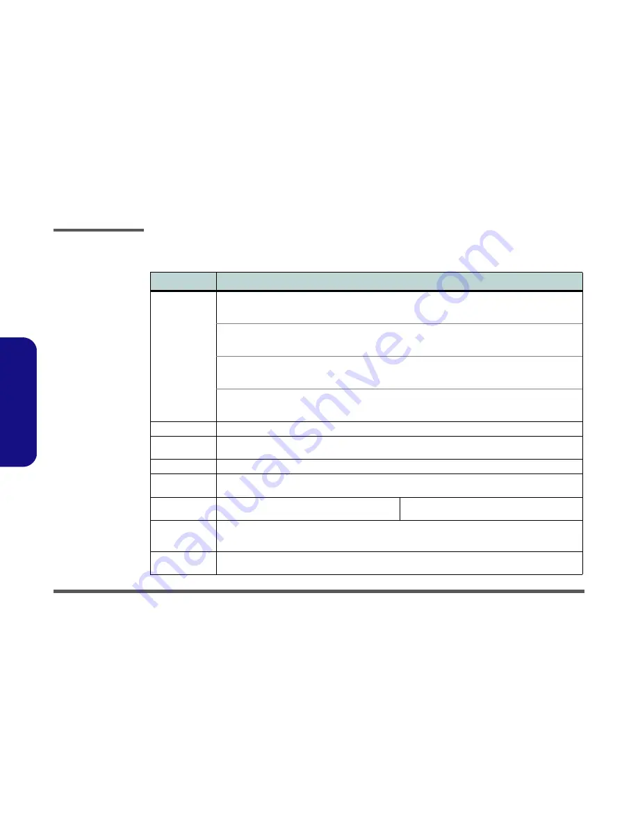
Feature
Specification
Processor Types
Intel® Core™2 Duo Processor
(478-pin) Micro-FC-PGA Package, 25W
P8400 / P8600
45nm (45 Nanometer) Process Technology
3MB On-die L2 Cache & 1066MHz FSB
2.26GHz / 2.4GHz
Intel® Core™2 Duo Processor
(478-pin) Micro-FC-PGA Package, 25W
P9500
45nm (45 Nanometer) Process Technology
6MB On-die L2 Cache & 1066MHz FSB
2.53GHz
Intel® Core™2 Duo Processor
(478-pin) Micro-FC-PGA Package, 35W
T9400
45nm (45 Nanometer) Process Technology
6MB On-die L2 Cache & 1066MHz FSB
2.53GHz
Intel® Core™2 Extreme Mobile Processor
(478-pin) Micro-FC-PGA Package, 44W
X9100
45nm (45 Nanometer) Process Technology
6MB On-die L2 Cache
& 1066MHz FSB
3.06GHz
Core Logic
Intel(R) PM45 + ICH9M Chipset
Memory
Two 204 Pin SO-DIMM Sockets Supporting
DDRIII (DDR3
) 800 MHz / 1066 MHz
Memory Expandable up to 4GB
BIOS
One 2MB/ 4MB Flash ROM
Phoenix™ BIOS
Security
Security (Kensington® Type) Lock Slot
Fingerprint Reader Module (
Factory Option
)
BIOS Password
LCD Options
17" WXGA (1440 * 900) TFT LCD (Glare Type)
17" WXGA (1440 * 900) TFT LCD (Non Glare Type)
17" WUXGA (1920 * 1200) TFT LCD (Glare Type)
17" WUXGA +(1680 * 1050) TFT LCD (Glare Type)
Storage
One Changeable 12.7mm(h)
SATA
Optical Device (CD/DVD) Type Drive (see
“Optional” on page 1 - 4
for drive
options)
Easy Changeable 2.5" 9.5 mm (h)
SATA
HDD
Card Reader
Embedded 7-in-1 Card Reader (MS/ MS Pro/ SD/ Mini SD/ MMC/ RS MMC/ MS Duo)
Note:
MS Duo/ Mini SD/ RS MMC Cards Require a PC Adapter
Summary of Contents for XMG7
Page 1: ......