background image

 Operations Manual 

Page | 20 

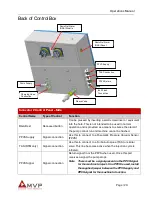
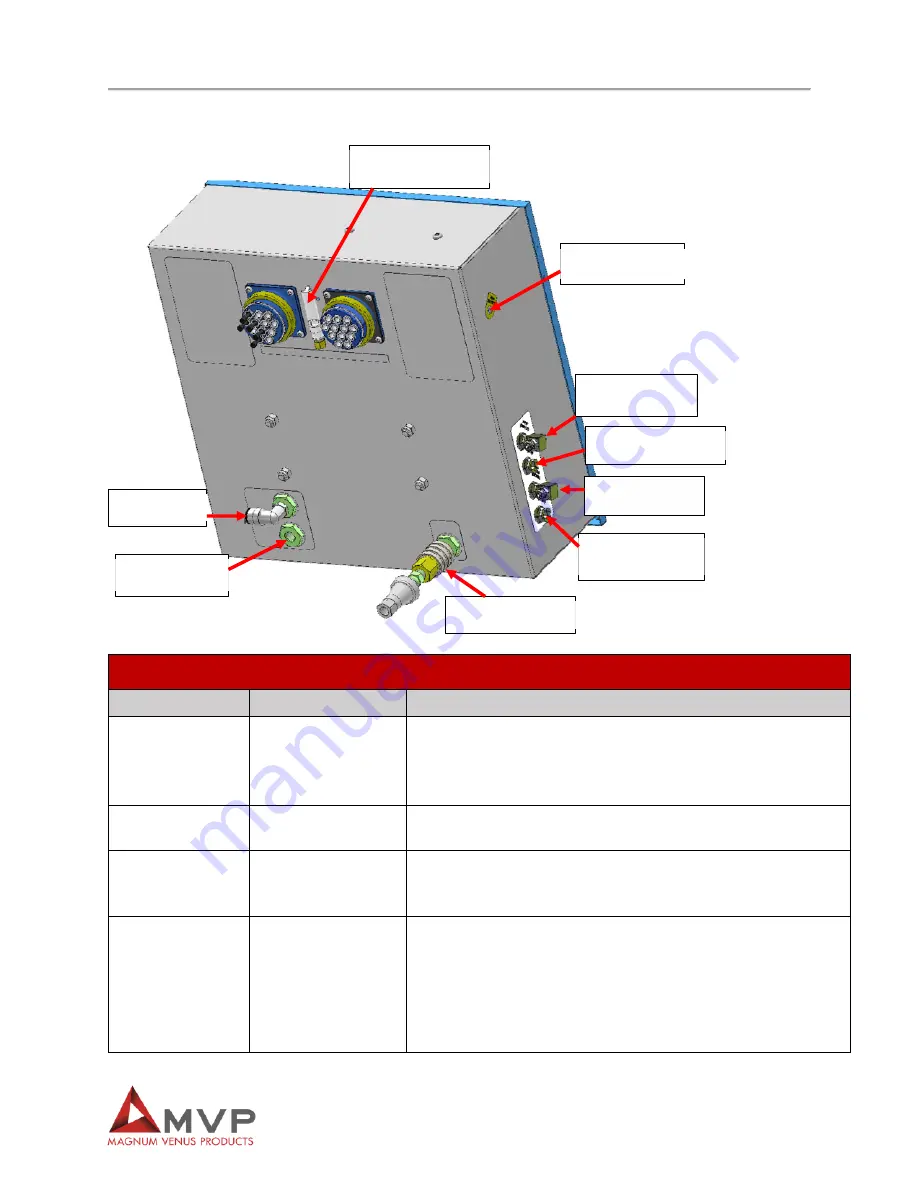
Back of Control Box 

Innovator 2 Control Panel – Side

Control Name 

Type of Control 

Function 

RGA Rest 

Recessed button 

Can be pressed by inserting a small screwdriver or equivalent 
into the hole. This is not intended to be used in normal 
operation and is provided as a means to silence the alarm if 
the pump cannot run and machine cannot be flushed.  

PPVS Supply 

Signal connection 

Use this to connect to a Pneumatic Pressure Vacuum Sensor 
(PPVS) 

TAS (RTM only) 

Signal connection 

Use this to connect to a Turbo Autosprue (TAS) or similar 
valve. This line becomes active when the injection cycle is 
initiated.  

PPVS Signal 

Signal connection 

Return signal from the PPVS when used. Once this port 
receives a signal the pump stops 

Note  There must be a signal present on the PPVS signal 

for the machine to inject. If no PPVS is used, install 
the supplied jumper between the PPVS supply and 
PPVS signal for the machine to function.  

Resin Gel Alarm 

(RGA) Whistle 

Resin Gel Alarm 

(RGA) Reset

Pump Supply 

Charging Hose 
Connection 

Sleeve Valve 

IVx3 Flush 

Connection 

PPVS Return 

TAS Connection 

PPVS Supply

Summary of Contents for INV2-PAT-7-PRO

Page 1: ...Patriot Pro Innovator 2 Operations Manual This manual is applicable to the following models INV2 PAT 7 PRO Rev November 2020 ...

Page 2: ...Knoxville TN 37932 USA Tel 865 684 4416 TECHNOLOGY CENTER AND MANUFACTURING 1862 Ives Ave Kent WA 98032 USA Tel 253 854 2660 Fax 253 854 1666 E mail info mvpind com For a list of international distributors visit our website at www mvpind com mvp international Use of this product confirms that Magnum Venus Products Inc s standard terms and conditions of sale apply ...

Page 3: ... 3 Table of Contents Section Page Table of Contents 3 Safety Warning Information 4 Introduction 15 Adjusting Settings 21 Getting Started 24 Performing a Gel Test 25 Performing Daily Tasks 26 Maintenance 27 Troubleshooting 28 ...

Page 4: ... Documentation 1910 94 Pertaining to ventilation 1910 106 Pertaining to flammable liquids 1910 107 Pertaining to spray finishing operations particularly paragraph m Organic Peroxides and Dual Component Coatings For Additional information contact the Occupational Safety and Health Administration OSHA at https www osha gov about html Recommended National Fire ProtectionAssociation NFPA Documentation...

Page 5: ... Cured laminate accumulations of overspray and laminate sandings are highly combustible Do not operate or move electrical equipment when flammable fumes are present Ground all equipment If a spark is seen or felt immediately halt operation Do not operate the equipment until the issue has been identified and repaired Contaminated catalyst may cause fire or explosion Containers may explode if expose...

Page 6: ...ical attention Inhalation Move the person to fresh air and seek immediate medical attention Do not remove shields covers or safety features on equipment that is in use Never place fingers hands or any body part near or directly in front of the spray gun fluid tip The force of the liquid as it exits the spray tip can shoot liquid through the skin Keep hands and body parts away from any moving equip...

Page 7: ...cates the risk of contact with moving components that may lead to serious injury or death Indicates that the system or component should be grounded before proceeding with use or repair Indicates the use of lit cigarettes or cigars is prohibited because the materials being used are susceptible to combustion Indicates that the materials and or the process being performed can lead to ignition and exp...

Page 8: ...an System Target Possible Target Known Possible Health Effect Aramid fibers Skin lungs Skin and respiratory irritation contact dermatitis chronic interstitial lung disease Carbon graphite fibers Skin lungs As noted for aramid fibers Glass fibers continuous filament Skin lungs As noted for aramid fibers Hardeners and curing agents Composite Component Organ System Target Possible Target Known Possib...

Page 9: ...losion of 12 acetylene and air The maximum value listed for a hydrogen explosion is 10 000 psi per second Some forms of MEKP if allowed to reach their SADT will burst even an open topped container This suggests that it is not possible to design a relief valve to vent this order of magnitude of pressure rate of rise The user should be aware that any closed container be it a pressure vessel surge ch...

Page 10: ...ditional recommendations by the catalyst manufacturer determines largely the safety that will be present in his operation Clean Up Solvents and Resin Diluents WARNING A hazardous situation may be present in your pressurized fluid system Hydro carbon solvents can cause an explosion when used with aluminum or galvanized components in a closed pressurized fluid system pump heaters filters valves spra...

Page 11: ...tion plans as Volatile Organic Compounds VOCs their low flammability hazard and their not being classified as toxic or carcinogenic substances HHC solvents are very desirable in many respects WARNING Do not use Halogenated Hydrocarbon HHC solvents in pressurized fluid systems having aluminum or galvanized wetted parts Magnum Venus Products is aware of NO stabilizers available to prevent HHC solven...

Page 12: ...ely to start a fire in addition the fire would burn hotter and longer Floor coverings if used should be non combustible Spilled or leaked catalyst may cause a fire if it comes in contact with an FRP product over sprayed chop or resin FRP sandings or any other material with MEKP To prevent spillage and leakage you should 1 Maintain your Magnum Venus Products System Check the gun several times daily...

Page 13: ...rea is free from dirt grease or resin Clean catalyst system components with clean water daily DANGER Eye skin and respiration hazard The catalyst MEKP may cause blindness skin irritation or breathing difficulty Keep hands away from face Keep food and drink away from work area Treatment of Chemical Injuries CAUTION Refer to your catalyst manufacturer s safety information regarding the safe handling...

Page 14: ...hen the ball valve handle is perpendicular across the ball valve body 2 Turn all system regulators to the OFF position counter clockwise position 3 Verify secure the catalyst relief line located on the catalyst relief valve 4 Verify secure the resin return line located on the resin filter 5 Place a container under the resin pump ball valve to catch ejected resin 6 Locate the ball valve on the resi...

Page 15: ...fully and retain for future reference Follow the steps in the order given otherwise you may damage the equipment or injure yourself Component Assemblies MVP s Patriot Pro Innovator 2 consists of multiple components Each component has its own detailed manual and drawings For complete repair and maintenance instructions refer to the appropriate manuals AUTO PRO GUN REPAIR MANUAL PRTM DG 3000 A INJEC...

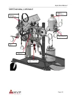
Page 16: ...ntify the main components the operator needs to know for proper operation for the unit Control Box Powerhead Catalyst Jug Catalyst Pump Flush Tank Resin Pump Resin Relief Valve Mold Pressure Guard MPG Static Mixer Flush Valve Injection Gun Recirculation Gun ...

Page 17: ...Operations Manual Page 17 Unit Overview continued Catalyst Recirculation Sight Catalyst Overpressure Catalyst Manifold MPG Slave Arm Surge Chamber and Filter ...

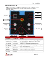
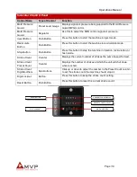
Page 18: ...and allow machine operation Pump Pressure Pressure Gauge Displays the air pressure being supplied to the pump Pump Pressure Regulator Adjust this to control the air pressure being supplied to the pump and to set the pump speed CAT OP Indicator Light Will turn red if overpressure state exists RGA Alarm Indicator Light Will turn red if gel alarm timer has expired Flush Button Push Button Press this ...

Page 19: ...on Push Button Press this button to stop the machine in injection recirculation or flush mode Stroke Count Counter Displays the current number of strokes the pump has performed Stroke Count Preset Count Counter Displays the number of strokes at which the unit will shut down when reached Stroke Count Digit Modifiers Spin Buttons Click up or down to adjust the number in the Preset Count column to se...

Page 20: ...uum Sensor PPVS TAS RTM only Signal connection Use this to connect to a Turbo Autosprue TAS or similar valve This line becomes active when the injection cycle is initiated PPVS Signal Signal connection Return signal from the PPVS when used Once this port receives a signal the pump stops Note There must be a signal present on the PPVS signal for the machine to inject If no PPVS is used install the ...

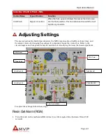
Page 21: ...lush timer duration the MPG response time the RGA stroke timer and the alarm volume by changing the settings of components inside the control box Refer to the circuit diagram and component labels for assistance in identifying the items that need adjustment To adjust the settings follow these steps Resin Gel Alarm RGA 1 Turn the knob on the mechanical RGA timer to set the required time between 20 a...

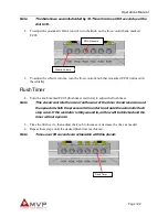
Page 22: ...imer restrictor to adjust the flush timer Note This circuit controls the rate of airflow out of the timer circuit reservoir and the speed at which the pressure fall in order to actuate the automatic flush stop valve If the restrictor is fully wound in air flow will be blocked and the timer will not operate 5 Time the flush cycle then adjust the knob to increase or decrease the time as needed 6 Rep...

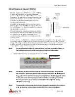
Page 23: ...ump is reduced in effect slowing it down Once the air pressure in the control circuit has dropped below approximately 15 psi the pump will shut off Once the pressure has been restored whether by fluid being drawn into the mold recirculation engage or blockage cleared from output line the system will start up again Note The MPG control is active in recirculation or injection mode It is normal to he...

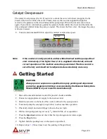
Page 24: ...n of the machine cannot be guaranteed This flow control is set at factory and should not be adjusted unless absolutely necessary Getting Started CAUTION Always put on respirator as specified for spray painting and all personal protective equipment clothing recommended by the Material Safety Data Sheets MSDS of your material manufacturer s 1 Have all tools and materials needed for pre start checks ...

Page 25: ... so that the pump strokes slowly and evenly 25 Allow the pump to recirculate until the flow of resin and catalyst back to their respective containers is free of bubbles 26 Press the Stop button to take the unit out of recirculation mode 27 Follow the steps in the Performing a Gel Test section before first use Performing a Gel Test 1 Check all material supplies and refill or replace as needed 2 Ope...

Page 26: ...entage is set properly 6 Check the resin pump pressure and adjust as needed 7 Set the desired number of counts on the stroke counter display 8 Make sure the catalyst pressure gauge reads above 115 to 145 psi 8 to 10 bar before beginning the injection 9 Press the Stop button to take the unit out of recirculation mode 10 Perform a gel test each morning and balance the fluid pressures by following th...

Page 27: ...an and purge the injection head and mixer It is contained within the flush tank During the flush cycle only the SP4 solvent pump will be pressurized to force out the solvent contained inside and then purges air for the remainder of the flush cycle There are two connection to the flush pump inside the flush tank The pump inlet air tube connects to the inlet side of the SP4 solvent pump through the ...

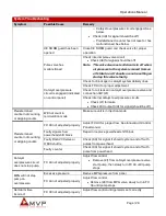
Page 28: ...oming from PPVS if installed Check internal PPVS circuits Check line 67 for leaks Check V08 output 41 for signal should be on Will not start injection or has stopped during injection sequence MPG circuit is engaged Check for blockage on resin delivery lines Check FC 03 for proper adjustment Will not start injection or has stopped during injection sequence Check for air leaks on MPG valve and conne...

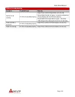
Page 29: ...ck V03 output 49 for signal should be off Predetermined counter not counting or skipping counts Will not count in recirculation mode Make sure unit is in injection mode Predetermined counter not counting or skipping counts FC 03 not adjusted properly Adjust FC 03 for proper flow See Innovator II Control Panel manual Faulty signals from powerhead shift block Repair or replace powerhead shift block ...

Page 30: ... RGA V02 51 for signal should be off pulsing when pumping and on when not pumping Check RGA V02 output 52 for signal should be off pulsing when pumping and on when not pumping Flush dwell time incorrect FC 05 not adjusted properly Adjust flow control until flush dwell is set correctly Flush not working FC 05 not adjusted properly Adjust flow control until flush dwell is set correctly ...

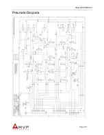
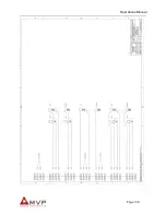
Page 31: ...Operations Manual Page 31 Pneumatic Diagrams ...

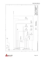
Page 32: ...Operations Manual Page 32 ...

Page 33: ...Operations Manual Page 33 ...

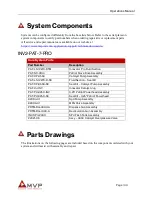
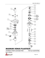
Page 34: ...100 Patriot Slave Drive Assembly PAT CP 0550 Catalyst Pump Assembly PAT LS 12270 R SK Fluid Section Seal Kit PAT CP 0550 SK Seal Kit Catalyst Pump Assembly PAT CJ INV Innovator Catalyst Jug PAT PH 3250 INV 3 25 Patriot Powerhead Assembly PAT PH 3250 SK Seal Kit 3 25 Patriot Powerhead 82004 01 Sp4 Pump Assembly 82009 01 MPG Valve Assembly PRTM DG 3000 A Dispense Gun Assembly PRTM RG 1000 A Recircul...

Page 35: ...Operations Manual Page 35 ...

Page 36: ...Operations Manual Page 36 ...

Page 37: ...Operations Manual Page 37 ...

Page 38: ...Operations Manual Page 38 ...

Page 39: ...Operations Manual Page 39 ...

Page 40: ...Operations Manual Page 40 ...

Page 41: ...Operations Manual Page 41 ...

Page 42: ...Operations Manual Page 42 ...

Page 43: ...Operations Manual Page 43 ...

Page 44: ...Operations Manual Page 44 ...

Page 45: ...Operations Manual Page 45 ...

Page 46: ...Operations Manual Page 46 ...

Page 47: ...Operations Manual Page 47 ...

Page 48: ...Operations Manual Page 48 ...

Page 49: ...Operations Manual Page 49 ...

Page 50: ...Operations Manual Page 50 ...

Page 51: ...Operations Manual Page 51 ...

Page 52: ...Operations Manual Page 52 ...

Page 53: ...Operations Manual Page 53 ...

Page 54: ...Operations Manual Page 54 ...

Page 55: ...Operations Manual Page 55 ...

Page 56: ...Operations Manual Page 56 ...

Page 57: ...Operations Manual Page 57 ...

Page 58: ...Operations Manual Page 58 ...

Page 59: ...STRIBUTION AND PURCHASING 642 Barbrow Ln Knoxville TN 37932 USA Tel 865 684 4416 TECHNOLOGY CENTER AND MANUFACTURING 1862 Ives Ave Kent WA 98032 USA Tel 253 854 2660 Fax 253 854 1666 E mail info mvpind com For a list of international distributors visit our website at www mvpind com mvp international ...

Reviews: