background image

DisplayPort 1.2a Fiber Extender Kit 

Installation Guide


© MuxLab Inc. 2016 

4.3 Connection Procedure 

a) 

Connect the Transmitter to the source equipment (such as the PC), and connect 
the Receiver to the sink equipment (such as a display). Power on the DisplayPort 
source and display. Both the Transmitter and Receiver will be turned on due to the 
3.3V supplied by pin #20 of DisplayPort interface. Even though the units are being 
powered, it is recommended that the USB Power Supplies be used as well as a 
more  stable  power  source  for  both  the  Transmitter  and  Receiver,  since  some 
source and display equipment may not be capable of providing sufficient power.   

b) 

The Power LED will illuminate when the 500502 is connected to the DisplayPort 
interface of the source and display, and the Status LED will blink three (3) times. 
After which the Status LED will blink again once a reliable link is established with 
the end equipment. 


c) 

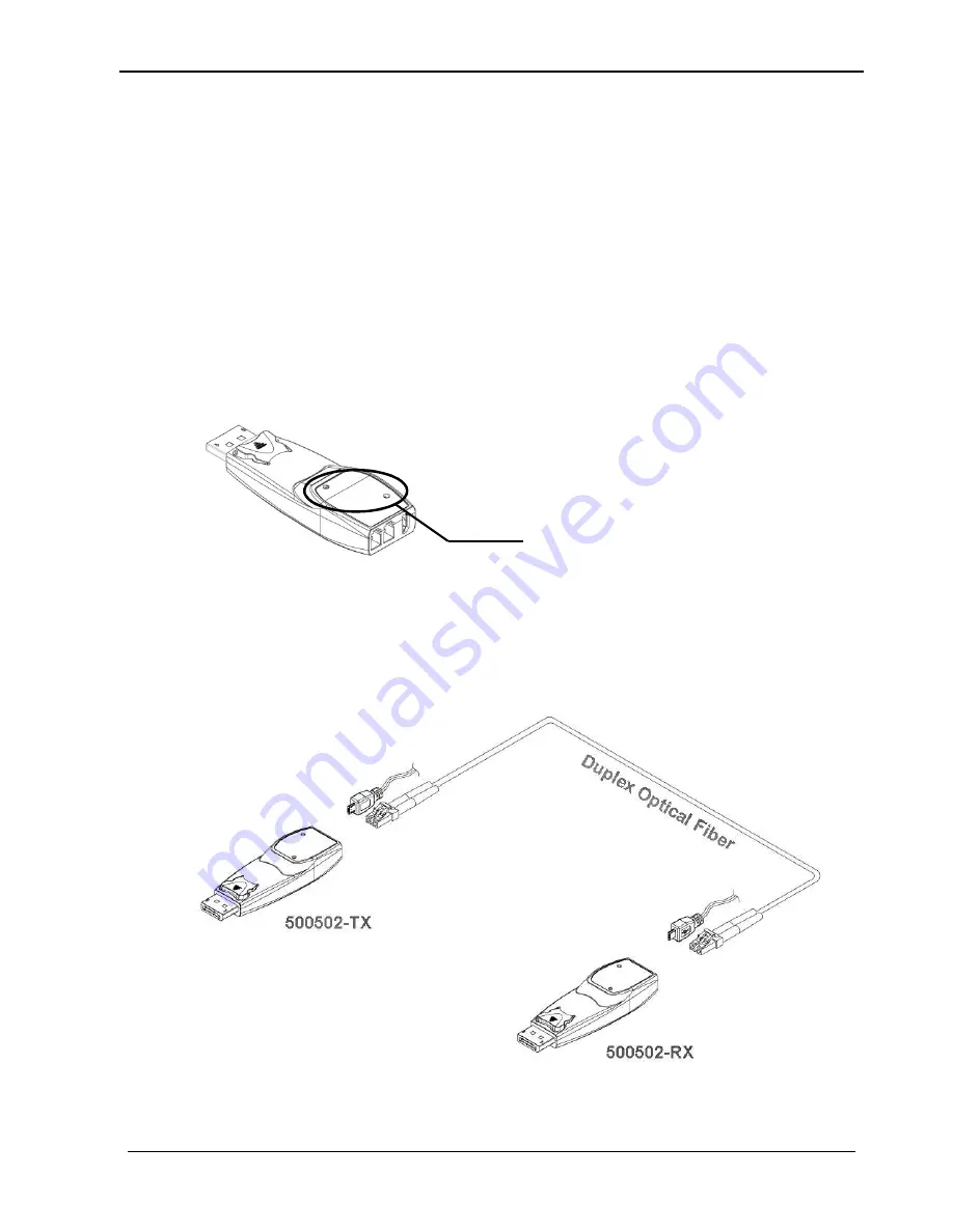
Connect  an  LC  terminated  duplex  optical  fiber  between  the  Transmitter  and 
Receiver, where each of the individual fibers are connected as (A) to (A) and (B) to 
(B). Ensure the duplex connectors are fully inserted and the top LED will begin to 
blink. 


Position of the LEDs 


Summary of Contents for 500502

Page 1: ... MuxLab Inc 2016 94 000840 A SE 000840 A DisplayPort 1 2a Fiber Extender Kit Installation Guide 500502 ...

Page 2: ...rosol cleaners to clean this unit Always unplug the power to the device before cleaning Using supplies or parts not meeting the product s specifications may cause damage deterioration or malfunction Refer all servicing to qualified service personnel Install the device in a place with good ventilation to avoid damage caused by overheating Unplug the power cord when left unused for a long period of ...

Page 3: ...nts 4 2 Specification 5 3 System Requirement for Installation 5 3 1 Hardware requirements 5 3 2 Software requirements 7 3 3 AC DC Power Adapter Technical Advisory 7 4 System Connection 7 4 1 Safety Precautions 7 4 2 System Diagram 7 4 3 Connection Procedure 8 5 Troubleshooting Maintenance 10 Maintenance 11 Technical Support and Service 11 Regulatory Compliance 12 ...

Page 4: ...om the 3 3V supplied from pin 20 of the DisplayPort connector of the source and display equipment Note that if the source or display equipment does not adequately supply this power on its DisplayPort connector then the included power supply must be used 1 2 Features Supports the DisplayPort 1 2a standard Up to 330ft 100m over 50 125 m multi mode fiber OM3 at WQUXGA 3840x2400 resolution 60Hz refres...

Page 5: ...ical Power output 1dBm Wavelength Min 825nm Max 990nm Total Optical Attenuation include cable and insertion attenuation 1 5dB Max at 330 ft 100 meters Insertion Attenuation 0 5dB Modal bandwidth Min 500 MHz Km λ 850 nm Extension Distance 10 1650ft 500 meters Power Supply Two 2 110 240V to 5VDC 1A power supply with interchangeable blades for US UK Euro Temperature Operating 0 to 50 C Storage 30 to ...

Page 6: ...nstallation Guide MuxLab Inc 2016 6 DisplayPort 1 2a Fiber Extender Kit 2 No special requirements for memory size CPU speed and chipsets are needed assuming the DisplayPort graphic controllers or cards have already been properly installed ...

Page 7: ...s can provide power to both the Transmitter and Receiver Although the DisplayPort interface of the source and sink device typically provides 3 3VDC on pin 20 of the DisplayPort connector the USB power supply option is recommended as a more stable power source for both the Transmitter and Receiver 4 System Connection 4 1 Safety Precautions This system should be installed in a clean environment with...

Page 8: ...ell as a more stable power source for both the Transmitter and Receiver since some source and display equipment may not be capable of providing sufficient power b The Power LED will illuminate when the 500502 is connected to the DisplayPort interface of the source and display and the Status LED will blink three 3 times After which the Status LED will blink again once a reliable link is established...

Page 9: ...se of any intermediate cable or adapter between these units or between these units and the end equipment to avoid any undesirable performance degradation a Connect the Transmitter directly to the DisplayPort connector of the source Computer b Connect the Receiver directly to the DisplayPort connector of the display c These units should be connected together with a single length of duplex multimode...

Page 10: ...rly booted Ensure that the duplex fiber is properly inserted into both the Transmitter and Receiver Reset the system by disconnecting and reconnecting the Transmitter DisplayPort or Receiver DisplayPort side units or by disconnecting and reconnecting the USB power cables that are plugged in the Transmitter and Receiver modules If necessary try to re boot the system and re connect the DisplayPort 1...

Page 11: ...l service and repair issues to MuxLab Technical Support and Service For commercial or general product support contact your reseller For technical service contact MuxLab by email videoease muxlab com or visit MuxLab s website at www muxlab com Certification of Eye Safety This laser component is using the following wavelength 825 850 930 950 980nm LD Transceivers which are all certified by CDRH FDA ...

Page 12: ... in no event be liable for any loss of profit or any other commercial damage including but not limited to special incidental consequential or other damages No part of this document may be reproduced or transmitted in any form by any means electronic or mechanical including photocopying recording or information recording and retrieval systems without the express written permission of the manufactur...

Page 13: ...er Extender Kit Installation Guide MuxLab Inc 2016 13 8495 Dalton Road Mount Royal Quebec Canada H4T 1V5 Tel 514 905 0588 Fax 514 905 0589 Toll Free North America 877 689 5228 E mail videoease muxlab com URL www muxlab com ...

Reviews: