background image

© MuxLab Inc. 

Passive CCTV/GLI Hub Installation Guide 


Page 12 

Output Connections: 

Video:


7.


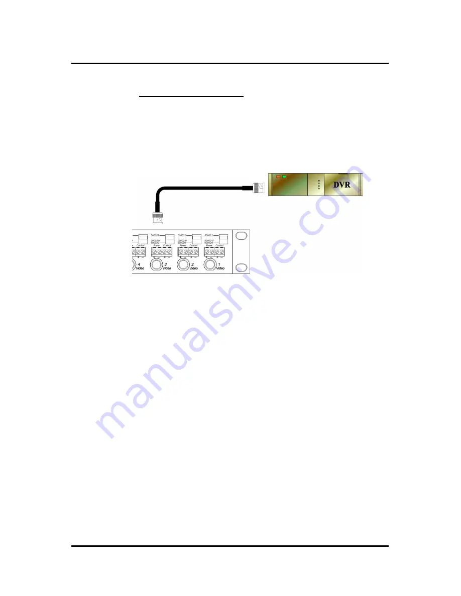
Connect one coax cable between each video output 
port on the rack and the DVR video input (fig 8).  


Figure 7: Video connection 

Remote Power:


8.


If remote power is being transmitted to the camera, 
verify that the distance between the camera and the 
hub is within MuxLab specifications.  Please consult 
the distance charts at the back of the installation 
guide.  When the port switch is set to Pass-Thru 
Mode (500022), two (2) twisted pairs are used for 
remote power.  When the port switch is set to Power-
Thru Mode (500024/500029), three (3) twisted pairs 
are used for remote power thus supporting greater 
distance. 

Summary of Contents for 500133

Page 1: ...VideoEase Passive CCTV GLI Hub 500133 Installation Guide P N 94 000619 A SE 000602 A ...

Page 2: ... 8 3 5 Installation Procedure 9 4 Troubleshooting 15 5 Distance Tables 17 6 Product Warranty Policy 18 Copyright Notice Copyright 2008 MuxLab Inc All rights reserved Printed in Canada No part of this publication may be reproduced stored in a retrieval system or transmitted in any form or by any means electronic mechanical photocopying recording or otherwise without prior written permission of the ...

Page 3: ...und Loop Isolation GLI on every port and therefore is applicable where there are voltage differences in ground level The Passive CCTV GLI Hub works in conjunction with MuxLab s 500000R 500009 500015 500022 500023 500024 500029 500120 and 500122 Each port on the product may be set to Power Thru or Pass Thru mode via 2 position slide switch 1 2 Features Ground Loop Isolation GLI on every port Slide ...

Page 4: ...ance B W Cat 3 1 500 ft 457m Cat 5 2 500 ft 762m Remote Power Switch Mode Pass Thru Mode 500022 Power Thru Mode 500024 500029 Number of twisted pairs Two 2 Three 3 Max Distance 24VAC Based on 10 voltage drop at camera Longer distances may be achieved 28 VAC 5 VA 350 ft 107m 10 VA 175 ft 53m 20 VA 90 ft 30m 30 VA 60 ft 20m 5 VA 518 ft 170m 10 VA 259 ft 85 m 20 VA 130 ft 43 m 30 VA 86 ft 28 m Maximu...

Page 5: ...ew terminals Combined signals Sixteen 16 RJ45 jacks Port Configuration Switch Sets each port to Pass Thru Mode 500022 or Power Thru Mode 500024 500029 RJ45 Pin Configuration Signal 500022 Mode 500024 500029 Mode Power A 1 3 1 3 5 Reverse polarity sensitive Power B 2 6 2 4 6 Control 4 Not used Control 5 Not used Video BNC Center Tip 7 T same as 500000R 7 T same as 500000R Video BNC Ground Ring 8 R ...

Page 6: ...s Please verify that all pieces are present before proceeding Base Unit Factory configuration Power Thru Mode 500022 Installation Guide 3 2 Product Overview The external connections of the Passive CCTV GLI Hub are detailed in the following diagrams Please familiarize yourself with them before installing the unit Figure 1 Front panel Figure 2 Rear panel ...

Page 7: ...each port and is connected to the DVR via coaxial cable and features a switch at each port to select between Pass Thru Mode 500022 compatible or Power Thru Mode 500024 500029 compatible depending on the cabling configuration 3 The Passive CCTV GLI Hub works in conjunction with MuxLab s other CCTV products including the 500000 500009 500015 500022 500023 500024 500029 500120 and 500122 The passive ...

Page 8: ...ation The Passive CCTV GLI Hub is a 1U 19 rackmount unit The factory default switch settings of each port is Pass Thru Mode 500022 1 Select the final destination for the product in the relay rack and install the unit using standard rackmount screws Figure 3 Rack mount installation ...

Page 9: ...between the rack and cameras are within MuxLab specifications 2 Connect a MuxLab passive CCTV GLI Balun MuxLab p n 500000 500009 500022 500023 500024 or 500029 to each CCTV camera video output Please refer to the appropriate CCTV balun installation guide for details 3 Connect one Cat5 cable from each camera to one of the modular RJ45 ports on the front of the Passive CCTV GLI Hub fig 5 Please ensu...

Page 10: ...pair remote power on two 2 twisted pairs and control on one 1 twisted pair set the port switch to Pass Thru Mode 500022 using a small flathead screwdriver as shown in fig 6 Ensure that there is a CCTV Pass Thru Balun 500022 at the camera Figure 5 Port Setting Pass Thru Mode 500022 6 In order to transmit video on one 1 twisted pair and remote power on three 3 twisted pairs set the port switch to Po...

Page 11: ... MuxLab Inc Passive CCTV GLI Hub Installation Guide Page 11 Figure 6 Port Setting Power Thru Mode 500024 500029 ...

Page 12: ...er is being transmitted to the camera verify that the distance between the camera and the hub is within MuxLab specifications Please consult the distance charts at the back of the installation guide When the port switch is set to Pass Thru Mode 500022 two 2 twisted pairs are used for remote power When the port switch is set to Power Thru Mode 500024 500029 three 3 twisted pairs are used for remote...

Page 13: ...tance between the camera and the hub is within the distance specifications for sending PTZ control over twisted pair Consult the PTZ equipment vendor for maximum distances Please ensure that the port switch is set to Pass Thru Mode 500022 When the port switch is set to Pass Thru Mode 500022 one 1 twisted pair is used for PTZ control For optimum results it is recommended to use control protocols su...

Page 14: ...TV GLI Hub Installation Guide Page 14 Figure 10 PTZ connection 12 Power on the CCTV equipment cameras remote power supply PTZ controller 13 The following diagram shows a typical configuration Figure 11 Typical Configuration ...

Page 15: ... Picture Probable Causes Possible Solutions Power off Check power supplies of CCTV equipment Check power supply fuse Wrong pin configuration Check pin configuration and verify straight through wiring No video image Defective CCTV Balun Change CCTV baluns for another pair Poor image quality distortions interference EMI interference Wires reversed on signal pair on one side Split pair Check that wir...

Page 16: ...ignal pair must be twisted Picture loses color faded or weak Lower grade UTP cable is introducing high signal losses Use signal repeater for extended distance or replace cable by higher grade Wrong pin configuration Check wiring No power or intermittent power at camera Distance exceeded Verify distance specifications for remote power Move power closer to camera PTZ controls not responding Wrong pi...

Page 17: ...mera 20 21 60 86 28 5 21 60 922 302 10 21 60 461 151 28 VAC PSU 24VAC camera 20 21 60 230 76 Power Thru Mode 500024 500029 Three Twisted Pairs Voltage Pcam W Vcam1 min V Dist Spec2 max Feet Dist Spec2 max m 5 10 80 130 43 12 VDC AC PSU 12VDC AC camera 10 10 80 65 21 5 21 60 518 170 10 21 60 259 85 24 VAC PSU 24VAC camera 20 21 60 130 43 5 21 60 1382 454 10 21 60 691 227 28 VAC PSU 24VAC camera 20 ...

Page 18: ...e location and to use the original shipping container or equivalent THE ABOVE LIMITED WARRANTY IS THE ONLY WARRANTY COVERING YOUR MUXLAB PRODUCT THERE ARE NO OTHER WARRANTIES EXPRESSED OR IMPLIED INCLUDING WARRANTIES OF MERCHANTABILITY OR FITNESS FOR A PARTICULAR PURPOSE SOME STATES DO NOT ALLOW LIMITATIONS ON IMPLIED WARRANTIES SO THE ABOVE LIMITATION MAY NOT APPLY TO YOU IF THIS PRODUCT IS NOT I...

Page 19: ...t will be repaired or if repair is not possible replaced by an equivalent unit and returned to the customer within one 1 month of receiving any returned product There is no charge for repair parts and labor during the full warranty period Items Defective and not under Warranty For products which are no longer under warranty the policy is repair and return An amount of 25 of the products published ...

Page 20: ...MuxLab Inc 8114 Trans Canada Hwy St Laurent Quebec Canada H4S 1M5 Tel 1 514 905 0588 Fax 1 514 905 0589 Toll Free North America 877 689 5228 URL www muxlab com E mail videoease muxlab com ...

Reviews: