© MuxLab Inc. 2010
2.
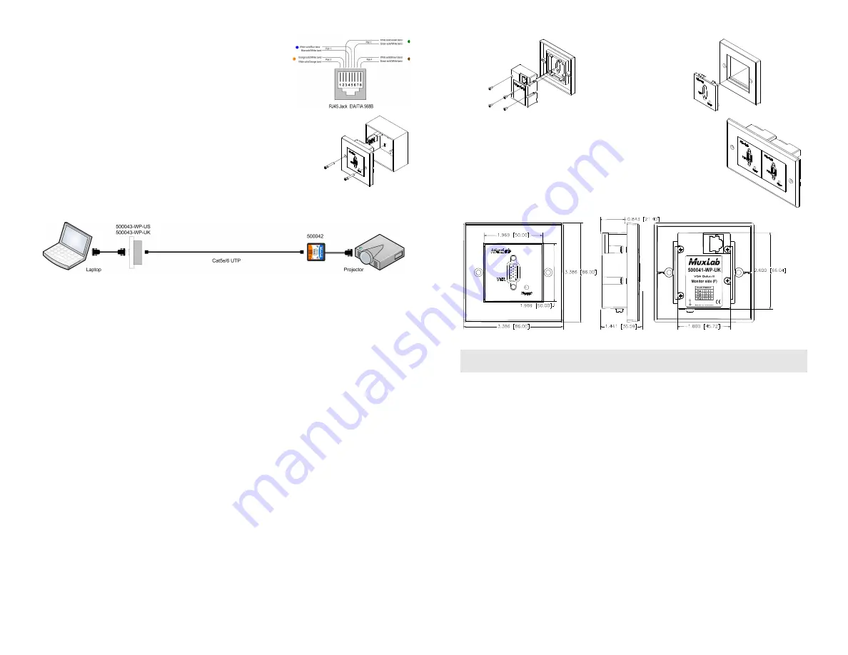
Connect a Cat 5E/6 4-pair cable from the modular RJ45
jack of the 500043 or 500043 to the twisted pair cabling
of the building. Wiring must be straight-through and
according to EIA 568A or 568B as shown in the
following diagram.
3.
To install the balun in a single back box, choose a back box
with a depth of 40 mm or more. Connect the RJ45 plug into the
rear of the balun. Secure the balun with the 2 front screws.
4.
Connect the 500041-WP-UK to the VGA input of the display
using a standard VGA cable.
5.
Power on the PC and VGA monitor. Set monitor Contrast and Brightness to the desired
levels. Set the monitor refresh rate to 60 Hz. See typical application below.
6.
Due to the fact that some displays are more sensitive than others and may not sync up
correctly, a RESET button is provided on each VGA Wall Balun or VGA Balun II to
allow these displays to re-synchronize. A RESET button is on both the transmit and
receive side baluns for greater convenience and ease of access. If the initial setup yields
an improperly positioned image on the screen, using a pen or small screw driver, press
the RESET button located next to RJ45 jack on one of the baluns and then immediately
press the AUTOSET button located on the display unit. During this time the image will
change hue and gradually return to normal after approximately fifteen (15) seconds.
Note:
Some displays do not require the AUTOSET button to be pressed.
7.
Set monitor Contrast and Brightness to the desired levels.
Note:
In order to avoid accidentally resetting the connection, the Screensaver options
under Windows Display Settings must be set as follows: (a) Choose any screensaver
except “NONE”; and (b) The “Turn Off Monitor” setting must be set to “NEVER”.
8.
The VGA Balun features an optional grounding screw (see diagram above) that may be
used to clear up any image anomalies. For example, under some conditions, there may
be a slight difference in hue between the left hand side of screen and the right.
Connecting the ground terminal to earth ground will help clear this up. However, if
there is a ground loop problem in the building, connecting the ground terminal may
negatively affect the image. Therefore the ground screw should only be used if it
improves the overall image quality.
Note:
During start-up, there may be a two (2) to three (3) second delay before an image
appears and the initial image may have a yellow hue. This is a normal function of the
product and is required in order to allow the monitor to sync up correctly.
9.
To mount the wall plate balun in a gang plate, you must first remove the rear 4 screws,
then remove the balun. Then unclip the balun front plastic panel.
10.
Clip the front plastic panel to a standard gang plate and secure
the balun using its 4 screws. Multiple wall baluns can be
mounted side by side on a gang plate.
Front view
Side view
Rear view
Troubleshooting
The following table describes some of the symptoms, probable causes and possible
solutions in respect to the installation of the VGA Balun II:


