


VJ-1204 INSTALLATION MANUAL
VJ1204E-I-00
4
1
2
1
2
1
e
a
b
c
d
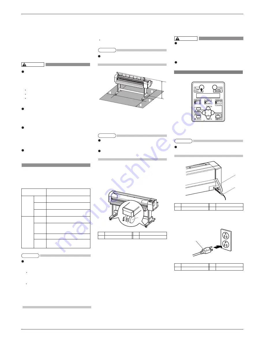
a=180mm
b=450mm
c=480mm
d=300mm
e=1198mm
4 Installation
Procedures and environment for installing this product
are explained.
4.1 Installation environment
Install this product to the appropriate place with refer-
ence to the following.
Do not install the printer in the follow-
ing places where there is a possibility
that the printer may be damaged or
might fall or be fallen by chance.
On a shaky stand
Slanting location
Places where vibration of other machines
etc. is transmitted.
Do not stamp on the printer or do not
place heavy things on top of it. The
printer may be damaged or might fall
or be fallen by chance.
Cover the printer with blanket and
cloth like tablecloth and do not close
the vent. If the vent is closed, the print-
er could accumulate heat inside and
may cause fire.
Do not install the printer in a location
that has high humidity or is dusty.
It could lead to electric shock and fire.
4.1.1 Installation environmental condition
Select an installation location in accordance with the
table below.
For temperature and humidity, avoid locations
such as the following. There is a possibility that
the print quality will be affected.
Places where temperature or humidity may
rapidly change, even though within the required
conditions.
Places that receive direct sunlight, increased illu
mination or direct air, for example from an air
conditioner.
To keep the temperature and humidity constant, in-
stall this product in a location where the air condi-
tion is adjustable.
4.1.2 Installation space
Install on a level floor which meets the following con-
dition.
It has enough strength to support the weight of the
printer and the stand.
For the weight of the printer and the stand, refer to
the Operation Manual.
4.1.3 Installation procedure
Install this product to the installation place in accord-
ance with the list shown below.
Please check that the butterfly bolts are not loose
before/after carrying this product.
When transferring or carrying outside, separate the
printer and the stand.
1. Check that the two butterfly bolts attaching the
stand and the printer are not loose.
2. Carry the plotter to the installation place.
3. Lock two casters on the front side.
4. Check that the two butterfly bolts attaching the
stand and the printer are not loose.
5 Connecting the power cable
This section explains how to connect the power cable.
Make sure that the included power ca-
ble is used.
If other power cables are used, it may
cause an electric shock or fire.
Do not use a damaged power cable. It
may cause an electric shock or fire.
Follow the steps below to connect the power cable.
1. Confirm that the product is turned OFF.
If the [Power] key is pressed, the product is turned
ON. Press the key again, and turn OFF the power.
2. Connect the power cable to the AC inlet on the
back of the product.
3. Correctly insert the power cable plug into the pow-
er socket.
More than 2940 Pa (300 kg/m
2
)
Power
Specifica-
tion
Environm-
ental
conditions
Floor strength of
installation place
Power
Supply
Frequency
Range
AC90V - 132V/198V - 264V
50/60Hz ± 1Hz
Power
capacity
Change
rate
Operative
condition
Archiving
environment
Guaranteed
range of
printing
accuracy
More than 10 A
Temperature:20 °C to 32 °C
Humidity: 40 % to 60 %, No Condensation
Temperature:22 °C to 30°C
Humidity: 40 % to 60 %
Temperature: within 2 °C per hour
Humidity: within 5 % per hour
Temperature:-20° C to 60 °C
Humidity: 5 % to 85 % ,
No Condensation (Ink unfilled)
No.
Name
1
Casters
No.
Name
2
Caster locks
No.
Name
1
AC inlet
No.
Name
1
Power cable
NOTE
NOTE
NOTE
WARNING
WARNING
NOTE


