
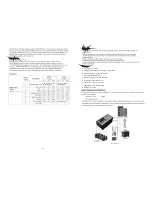
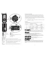


1. BAT -
2. BAT +
3. RS232
communication
port
4. Remote
port
5. FAN
6. AC
input/Bypass
breaker
7. AC
output
breaker
8. GND
9. PV1
input
10. AC
input
11. AC
output
12. Function
Switch(SW1~SW5)
13. AGS
11
10
9
8
6
7
3
5
12 4
1
13
5
15
14. BTS
15. AC Output 10A(MAX)
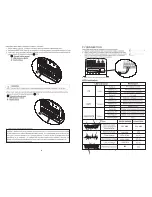
L
N
N
L
AC
IN
AC
OUT
PV
IN
+ -
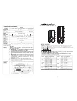
OUTPUT
12VDC
24VDC
Battery
Voltage
48VDC
RS232
AGS
BTS
REMOTE
PORT
1
0
SW1
SW2
SW3
SW4
SW5
Battery
Negative
Battery
Positive
Earth
2
14
ON(Power Saver)
INVERTER OFF
ON
16
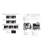
Line Mode
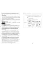
When utility is the unit the battery from the utility,LCD indicate charge current:
In utility mode the unit provide output power from the utility, the indication and displays are
following figures:
In battery mode the unit will provide output power from battery or PV, LCD
:
indicate battery capacity
Summary of Contents for PV3000 PK
Page 1: ......


