background image

ASSEMBLY

7

F-050204L

HOW TO RAISE THE HANDLE

1. Hold the

 handle

 with one hand and loosen both 

handle adjustment knobs

 until the ratchet

teeth are disengaged. Do not remove the 

handle adjustment knobs

. See Figure 2.

2. Raise the

 handle

 to the

operating position.

3. Stand in the operator’s

position behind the trim-

mer. Put the

 handle 

in a

comfortable position.

Make sure both sides  of

the

 handle

 are level.

NOTE:  Make sure the

cables are not caught

between the upper and

lower handle.

4. Tighten the 

handle ad-

justment knobs

. Make

sure the 

handle pivots

are locked in place.

NOTE:  The handle

height is adjustable.

See “How To Adjust

The Height Of The Han-

dle” in the Adjustment

section.

5. To attach the 

recoil start handle

 to the 

rope guide,

 twist the rope through

the 

rope guide

 mounted on the right side of the handle.

ENGINE PREPARATION

Note: Engine does not contain OIL or

GASOLINE.

WARNING: Follow the  engine

manufacturer’s instructions for

the type of gasoline and oil to

use. Always use a safety gasoline con-

tainer. Do not smoke when adding gaso-

line to the engine. When inside an en-

closure, do not fill with gasoline. Before

you add gasoline, stop the engine. Let

the engine cool for several minutes.

See the engine manufacturer’s instructions

for the type of gasoline and oil to use. Before

you use the unit, read the information on

safety, operation, maintenance, and storage.

Note: Actual sustained horsepower will

likely be lower due to operating limita-

tions and environmental factors.

Fill Crankcase With Oil

1. Remove the oil fill cap/dipstick shown in

Figure 3. Fill the crankcase to the 

FULL

line on oil fill cap/dipstick. 

DO NOT OVER-

FILL.

2. Install the oil fill cap/dipstick and tighten

securely.

Fill Fuel Tank With Gasoline

See the engine manufacturer’s instructions for

the type of gasoline to use. 

Figure 3

Fuel

Cap

Oil Fill

Cap/Dipstick

Figure 2

Handle

Handle Adjustment

Knob

Handle

Pivot

Recoil Start

Handle

Rope

Guide

Summary of Contents for TM6100X5A

Page 1: ...laws and other laws are followed PRODUCT INFORMATION This Instruction Book contains information for several models Read and keep this book for future reference This book contains important information on SAFETY ASSEMBLY OPERATION AND MAINTENANCE RECORD THE FOLLOWING INFORMATION ABOUT YOUR UNIT THIS INFORMA TION IS NECESSARY WHEN ORDERING PARTS OR IN CASE OF LOSS OR THEFT F 050204L Model TM6100x5A ...

Page 2: ...id or does not apply to any unit that has been tampered with altered misused abused or used for rental or other commercial and or professional non homeowner uses Your warranty does not cover minor mechanical adjust ments which are not due to any defect in material or workmanship For assistance in making such adjustments consult your Instruction Book To make a claim under this Murray Inc Two 2 Year...

Page 3: ...roper guards or other safety protective devices in place 13 Use this equipment for its intended pur pose only 14 See manufacturer s instructions for proper operation and installation of accessories Only use accessories approved by the manufacturer 15 Operate only in daylight or good artificial light 16 Do not operate the trimmer while under the influence of alcohol drugs or other medica tion which...

Page 4: ...chine indoors d Never store the machine or fuel con tainer inside where there is an open flame such as a water heater 2 Never run an engine indoors or inside a closed area 3 Never make adjustments or repairs with the engine motor running Disconnect the spark plug wire and keep the wire away from the plug to prevent accidental starting remove the ignition key if equipped with an electric start Alwa...

Page 5: ...derstand the purpose for each symbol Control And Operating Symbols Slow Fast WARNING Thrown Objects Keep Bystanders Away WARNING Rotating Parts Stop Engine Disconnect Spark Wire Before Making Adjustments IMPORTANT Read Owner s Manual Before Operating This Machine WARNING STOP WARNING Wear Eye Protection Safety Warning Symbols WARNING Never Operate Up Or Down Slopes Operate Across Slopes Fuel Oil ...

Page 6: ... completely as sembled and positioned in the carton for ship ment References to the right or left hand side of the trimmer are from the viewpoint of the opera tor s position behind the unit TO REMOVE THE TRIMMER FROM CARTON 1 Remove the bottle of oil and parts bag from the carton 2 Remove the packing material positioned around the unit 3 Cut down all four corners of the carton and lay the side pan...

Page 7: ...IL or GASOLINE WARNING Follow the engine manufacturer s instructions for the type of gasoline and oil to use Always use a safety gasoline con tainer Do not smoke when adding gaso line to the engine When inside an en closure do not fill with gasoline Before you add gasoline stop the engine Let the engine cool for several minutes See the engine manufacturer s instructions for the type of gasoline an...

Page 8: ...ctly into the carburetor manifold for faster starts See Figure 7 Recoil Starter Handle The engine is equipped with an easy pull recoil starter Shield Edge Guard Protects the shield by automatically cutting the line to the correct length EYE PROTECTION WARNING Debris thrown from the trimmer can result in foreign objects being thrown into the eyes which can cause severe eye dam age Always wear safet...

Page 9: ...E THROTTLE CONTROL 1 During normal use set the throttle con trol lever in the FAST position to run the engine at full speed 2 Pull the throttle control lever back to de crease engine speed Push the throttle control lever forward to increase engine speed 3 To stop the engine pull the throttle con trol lever completely back to the STOP position Figure 6 Throttle Control Lever HOW TO USE THE PRIMER B...

Page 10: ...ins carbon monoxide an odorless and deadly gas Keep hands feet hair and loose clothing away from the trimmer and any moving parts on the en gine Avoid the muffler and sur rounding areas Temperatures may exceed 150 F Figure 8 Recoil Starter Handle TRIMMER TIPS WARNING Debris such as sticks gravel or rocks can be thrown with sufficient force to cause per sonal injury or property damage S Set the thr...

Page 11: ...ce with new line Note 2 Clean daily if used in extremely dusty or dirty conditions Note 3 Change more often if used in extremely dusty or dirty conditions PRODUCT SPECIFICATIONS Trimmer Line Diameter 0 155 inch Trimmer Line Length 21 5 inches Horse Power 6 GENERAL RECOMMENDATIONS The warranty on this trimmer does not cover items that have been subjected to operator abuse or negligence To receive f...

Page 12: ...oil when the engine is warm For the proper oil capacity see the en gine manufacturer s instructions 1 Disconnect spark plug wire from the spark plug 2 Remove the oil drain plug as shown in Figure 10 3 Drain all the engine oil into a flat pan 4 Install the oil drain plug Make sure the oil drain plug is tight 5 Remove the dipstick 6 Fill the engine crankcase DO NOT OVERFILL For proper oil capacity s...

Page 13: ...e IMPORTANT To extend the life of the trim mer line keep the trimmer line moist If not kept moist the nylon trimmer line will be come dry and brittle Keep extra trimmer line in a can of water The line will then stay flexible and easy to change A flexible line will also last much longer Figure 11 Trimmer Line Shield HOW TO CHANGE TRIMMER LINES When the trimmer line becomes worn to half the original...

Page 14: ...ndle are level 3 Tighten the knobs Figure 12 Ratchet Teeth Knob Handle HOW TO SET THE HEIGHT OF CUT CAUTION Before you set the height of cut stop the engine Wait for all moving parts to stop Allow the engine to cool and dis connect the spark plug wire The height of cut can be set from 1 1 2 inches to 3 inches Recommended cutting height for the average yard is 2 1 Use the T wrench found in the part...

Page 15: ...re 15 Do not bend the belt guides NOTE Make sure you replace the drive belt only with a replacement belt from the factory 5 To assemble the drive belt reverse the above steps Make sure all fasteners are tight Make sure the mounting bolt for the drive pulley is tight 6 Check the routing of the drive belt Make sure the drive belt is inside of all belt guides shown in Figure 15 IMPORTANT Test the dri...

Page 16: ...mation of acids during storage Acidic gas can damage the fuel system of an engine while in storage To prevent engine damage when the trimmer is in storage for 30 days or more follow the steps below S Let the engine run until it is out of gasoline S Drain the oil from the warm engine Fill the engine crankcase with new oil S Remove the spark plug from the cylinder Pour one ounce of oil into the cyli...

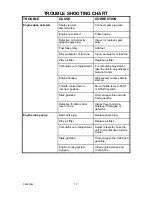
Page 17: ... to an authorized Service Center Engine flooded Wait several minutes before starting Throttle control lever in incorrect position Move throttle lever to FAST or START position Stale gasoline Drain old gasoline and add fresh gasoline Defective throttle control lever or wire Inspect lever and wire Replace if damaged or defective Engine runs poorly Bad spark plug Replace spark plug Dirty air filter R...

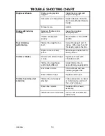
Page 18: ...s 21 5 inches When less than 1 2 this length replace the line Engine not set at FAST speed Move engine throttle lever to FAST position Trimmer vibrates Set screw for trimmer head is loose Tighten set screw with T handle wrench Trimmer line lengths are substantially different Adjust trimmer line to approximately equal lengths Loose nuts or bolts Check all bolts and nuts including engine bolts Broke...

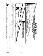
Page 19: ...t Use extreme care at all times and avoid sudden turns or maneuvers Follow other instructions in this manual for safety in trimming on slopes Operate a trimmer across the face of slopes never up or down slopes Use extra care when operating on or near slopes and obstructions 10 DEGREES 15 DEGREES Operate a trimmer across the face of slopes never up or down slopes SIGHT AND HOLD THIS GUIDE LEVEL WIT...

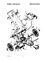
Page 20: ...MODEL TM6100x5A REPAIR PARTS 20 F 050204L 1 2 3 4 5 28 6 2 7 6 8 4 9 10 9 10 4 11 16 17 11 14 12 15 14 20 22 29 23 27 16 19 30 17 6 20 25 24 26 19 18 18 13 31 21 32 33 ...

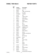
Page 21: ...her Spring 12 711937 Bolt 13 672292 Spacer 14 740158 Pivot Handlebar 15 740195E701 Handlebar Lower 16 740185 Wheel Tire 17 015x84 Nut Axle 18 0020x3 Washer Spring 19 740190 Spacer 20 740188 Assembly Axle Bracket 21 26x274 Screw 22 711935 Bolt Carriage 23 740150E276 Frame 24 025x6 Bolt 25 740192 Shield Trailing 26 001x45 Bolt 27 26x267 Screw 28 Engine 29 711890 Glasses Safety 30 015x88 Nut 31 16010...

Page 22: ...MODEL TM6100x5A REPAIR PARTS 22 F 050204L 1 2 3 4 5 6 7 8 9 10 11 12 13 14 15 16 1 17 18 19 20 22 23 24 25 26 27 29 30 31 33 38 31 ...

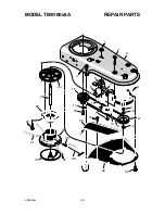
Page 23: ...ead 12 740173 Spacer Upper Pulley 13 711933 Belt Trimmer 14 740244 V Pulley 15 740179 Pulley Engine 16 740183 Pulley Idler 17 018x31 Lockwasher 18 001x20 Bolt 19 26x235 Screw 20 740167 Flap Debris 22 740205 Shield Trimmer 23 26x294 Screw 24 1001049 Housing Jackshaft 25 740300 Shaft Cutting Head 26 740163 Wrap Weed 27 712126 Screw 29 740175E276 Assembly Cutter Head Wrap 30 712127 Screw Set 31 74016...

Page 24: ...r Elmore Gem Idaho Kooten Latah Lewis NEZ Perce Owyee Payette Ravalli Shoshone Valley Washington Montana counties Flathead Lake Lincoln Mineral Missoulo Ravalli Sanders Oregon Washington CPT CANADA POWER TECHNOLOGY LIMITED Mississauga 161 Watline Avenue Mississauga Ontario L4Z 1P2 905 890 6900 1 800 861 9559 Edmonton 101 10411 178 Street Edmonton Alberta T5S 1R5 780 453 5791 1 800 861 9559 Ville S...

Reviews: