LR-9017N page 2 of 2
Connection of the LR857 must be made to the equipment crankcase at
the lowest possible point–usually the oil drain plug. Hoses, hose clamps
and supply tank are supplied by the customer. Also these instructions
are based on the Murphy optional fittings kit described on the reverse
side. If you did not order the fittings kit, gather the proper fittings as
specified on the reverse side.
1.
Determine the mounting location on or near the equipment for the
LR857. Mount the LR857 using the optional pipe mounting bracket
(15000238) or universal mounting bracket (15010224) or suitable cus-
tomer supplied mounting.
NOTE:
Mounting must allow vertical
adjustment of the LR857 to locate proper regulated level.
2.
Drain the crankcase and attach a 1/2 in. (13 mm) I.D. flexible hose from
the crankcase to the oil outlet port on the LR857.
CAUTION:
The hose
must slope slightly downward from the LR857 and
MUST NOT
have
any droop or low spots.
NOTE:
If the drain plug on the crankcase is
used for the connection, we recommend installation of a tee to allow
draining of the crankcase for service. All hoses should be as short in
length as possible.
3.
For sealed crankcases, connect a 1/4 in. (6 mm) O.D. tube from the
crankcase to the tube fitting on the LR857 (see drawing below).
For vented crankcases install the copper cane.
CAUTION:
The
crankcase vent connection
MUST BE
above the oil level so that the
tubing will not be restricted by oil splash, etc. Failure to install the tub-
ing or cane vent will result in improper operation and oil spillage.
BEFORE CONTINUING, VERIFY THAT ALL HOSE CLAMPS ARE TIGHT
4.
Refill the crankcase to the proper oil levels. Vertically adjust the
LR857 so that the pointer is consistent with the actual running oil level
in the crankcase. Check this level against the “add oil” marking on the
dip stick. To
determine the level at which you wish oil to be added,
either drain oil from the crankcase or slightly lower the LR857 mount-
ing so that the pointer/switch actuator will indicate the level at which
oil will be added. This can be estimated by lowering the LR857 an
amount equal to the difference between the “FULL” and “ADD”
marks on the dip stick. Tighten the mounting bracket.
5
. Connect a hose between the oil inlet of the LR857 and the oil supply
tank. The hose must maintain a downward slope and not have low
spots or droops. A minimum height of 2 ft. (0.6m) above the LR857 is
recommended. Maximum head is 25 ft. (7.7 meters) or 10 psi
(6.9 kPa) [0.69 bar].
NOTE:
We recommend a shutoff valve be
attached in the bottom of the supply tank. A filter screen between the
supply and the LR857 is also recommended.
6.
Before filling the supply tank with oil, be sure the tank is clean and dry
and the shutoff valve is closed. Also, be sure all hoses and clamps are
tight. Fill the tank with clean oil.
7.
After oil supply tank is full, open the shutoff valve.
8.
Make the proper electrical connections for the application. See contact
ratings on reverse side.
For vented crankcase use the
cane vent. For sealed
systems, vent must be
piped back to crankcase,
above oil level.
Shutoff
Valve
CLEAN Oil Supply Tank.
Height above LR recommended
2 ft. (0.6 m) minimum and
25 ft. (7.7 m) maximum
Wire to
switch
circuits
LR857
Oil Outlet
Electrical
Conduit
Crankcase
Oil
Inlet
NOTE:
LR857 shown mounted
using a pipe bracket.
TYPICAL INSTALLATION
WARNING:
Overfill condition can be caused by
excessive inlet pressure and/or improper “vent to
crankcase” installation.
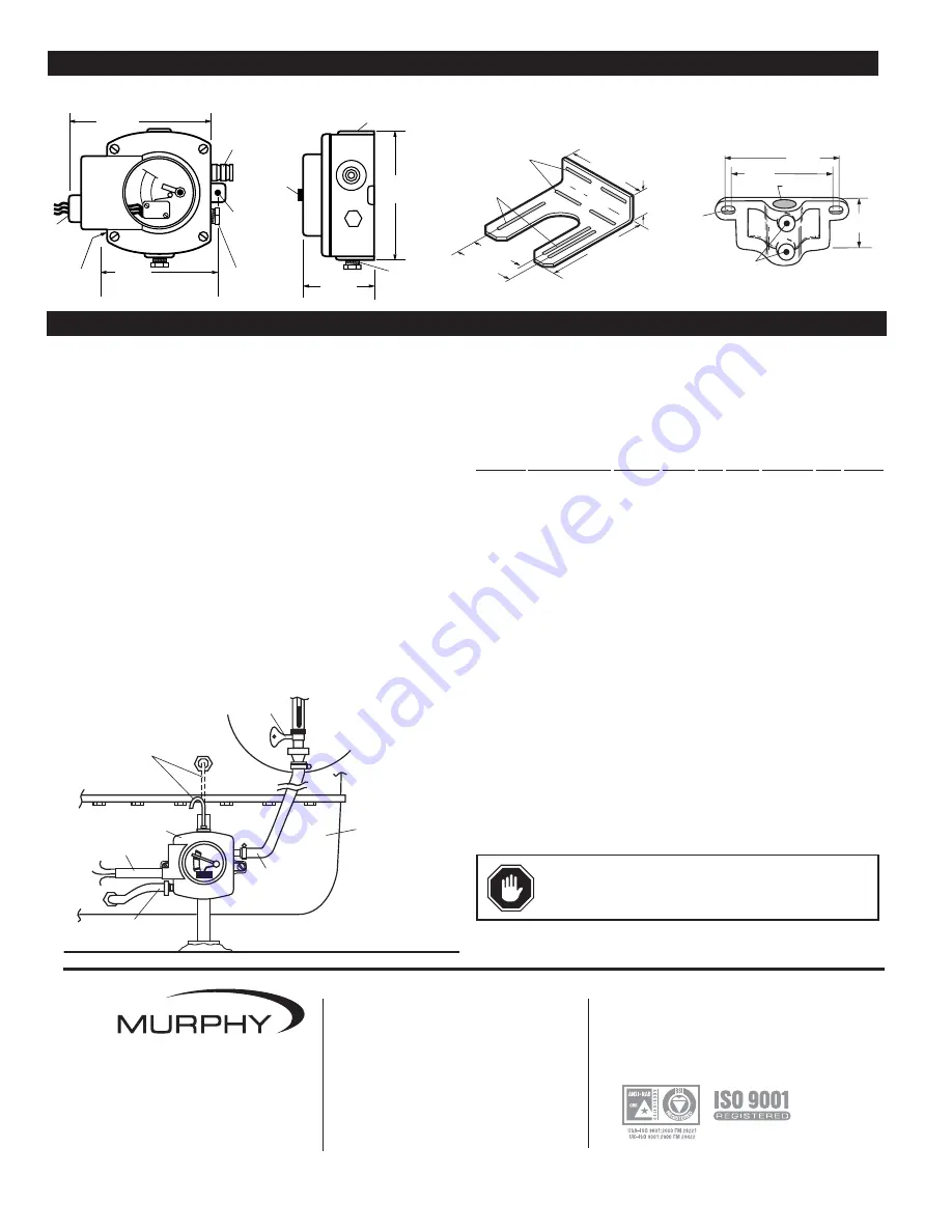
DIMENSIONS
4-15/16 in.
(125 mm)
4-1/2 in.
(114 mm)
Mounting Holes
9/32 in. (7 mm)
Diameter Holes
2 places
5/
8
in. (16 mm)
I.D. Inlet Hose
Connection
1/4 NPT Internal
Threads
Plug
3/
8
NPT
1/2 NPT
Electrical
Conduit
Connection
3/
8
NPT
Outlet
Connection
4-13/16 in.
(122 mm)
Plug
1/2 NPT
1/4 NPT
2-25/32 in.
(71 mm)
Test
Knob
Universal Flange Kit
(15010224)
Pipe Bracket Kit
(15000238)
LR857
1.75 in.
(44 mm)
7.50 in.
(191 mm)
Slot, .390 in. (10 mm)
x 4.71 in. (120 mm)
3 places
6.69 in.
(170 mm)
Slot, .390 in. (10 mm)
x 2 in. (51 mm)
4 places
4.50 in.
(114 mm)
5.19 in.
(132 mm)
4.50 in.
(114 mm)
5.20 in.
(132 mm)
2.50 in.
(64 mm)
Hole .88 in.
(22 mm) dia.
1/4-20 NC
2 places
.376 in.
(10 mm)
minimum
bottom surface
2 places
CONTROL SYSTEMS & SERVICES DIVISION
P.O. Box 1819; Rosenberg, Texas 77471; USA
+1 281 633 4500 fax +1 281 633 4588
MURPHY DE MEXICO, S.A. DE C.V.
Blvd. Antonio Rocha Cordero 300, Fracción del Aguaje
San Luis Potosí, S.L.P.; México 78384
+52 444 8206264 fax +52 444 8206336
Villahermosa 52 993 3162117
www.murphymex.com.mx
FRANK W. MURPHY, LTD.
Church Rd.; Laverstock, Salisbury SP1 1QZ; U.K.
+44 1722 410055 fax +44 1722 410088
www.fwmurphy.co.uk
In order to consistently bring you the highest quality, full featured products, we reserve the right to change our specifications and designs at any time.
FW Murphy
P.O. Box 470248
Tulsa, Oklahoma 74147 USA
+1 918 317 4100
fax
+1 918 317 4266
www.
fwmurphy
.com
Printed in U.S.A.
1190077


