background image

PUSH-IN FITTING INSTALLATION

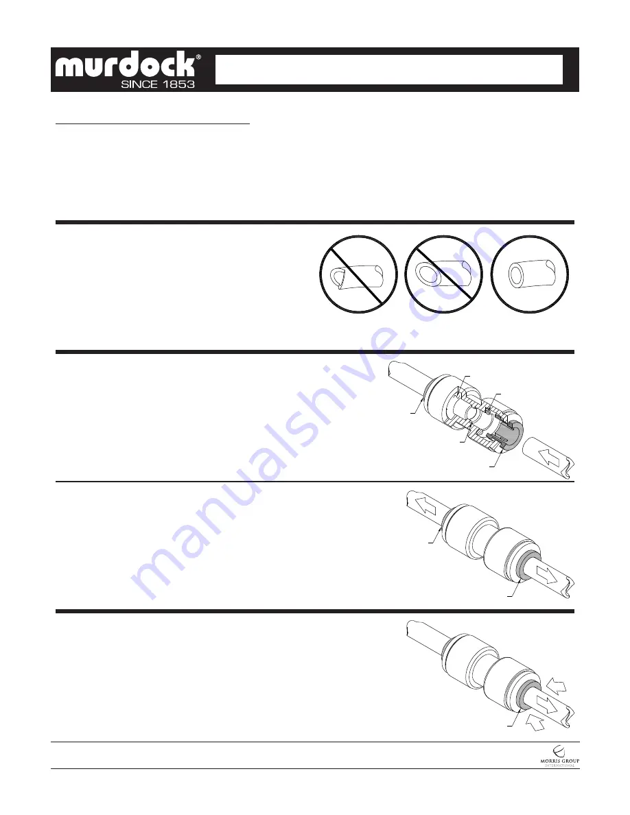
NOTE: FITTINGS AND TUBE SHOULD BE KEPT 
CLEAN, BAGGED AND UNDAMAGED PRIOR TO 
INSTALLATION.

2. Pull on the fitted tubing to ensure it is secure. Tube 

should not come free from the fitting. Water test the 
connection assembly prior to leaving the site to ensure 
there are no leaks.

DISCONNECTING THE TUBE:

To disconnect the tube from the fitting ensure that the 
water line is depressurized. Push collet square towards 
the push-in fitting body and hold. While holding the collet 
in, pull on the PE tubing to remove from the push-in fitting. 

TO CUT TUBE:

Cut to fit length of 1/4” PE tubing and remove any burrs 
or sharp edges. Ensure that the outside diameter is free 
from score marks. Tube ends should be square.

INSERTING THE TUBE:

1.   Firmly and fully insert the tubing end into the push-in 

fitting up to the tube stop located approximately ½” 
deep.

COLLET

COLLET

O-RING

O-RING

TUBE STOP

COLLET

COLLET

COLLET


A151.8-VR

Page 10 of 11

Date: 

11/10/2020

7021-024-001

MURDOCK  MFG.  • 

15125  Proctor  Avenue  •  City  of  Industry,  CA  91746  USA 

Phone  800-453-7465  or  626-333-2543  •  Fax  626-855-4860  •  www.murdockmfg.com

Member of

CONTEMPORARY WATER COOLERS


I N S TA L L AT I O N / M A I N T E N A N C E  I N S T R U C T I O N S

 DRINKING FOUNTAINS


Summary of Contents for A151.8-VR Series

Page 1: ...s not apply to materials which have been damaged by other causes such as mishandling or improper care or abnormal use The repair or replacement of the defective materials shall constitute the sole remedy of the Buyer and the sole remedy of Murdock under this warranty Murdock shall not be liable under any circumstances for incidental consequential or direct charges caused by defects in the material...

Page 2: ...h installation Adjust vertical dimension as required to comply with federal state and local codes For Child ADA compliant parallel approach decrease spout height to 30 maximum above finished floor Provide clear floor space as required A151 8 VR Page 2 of 11 Date 11 10 2020 7021 024 001 MURDOCK MFG 15125 Proctor Avenue City of Industry CA 91746 USA Phone 800 453 7465 or 626 333 2543 Fax 626 855 486...

Page 3: ...20 001 MURDOCK MFG 15125 Proctor Avenue City of Industry CA 91746 USA Phone 800 453 7465 or 626 333 2543 Fax 626 855 4860 www murdockmfg com Member of FINISHED FLOOR 293 8 SUPPLY INLET 291 2 WASTE OUTLET 383 8 BLOCKOUT 19 BLOCKOUT 2 57 8 C L 1 1 1 1 4 P Trap Waste Outlet 1 3 8 OD Supply Inlet 2 General Notes 1 Dimension indicated with is for 33 Drinking Fountain discharge height If discharge heigh...

Page 4: ... made following current Murdock Manufacturing installation instructions and if components are assembled to the fixture that is not approved by Murdock Manufacturing 1 Water Supply Service Angle Stop Valve and 2 x 4 Electrical Plug In Receptacle to be supplied by others in accordance with local codes A metallic P Trap must be used for the drain connection 11 Per UPC 609 10 All building water supply...

Page 5: ...ame 5 Remove the drinking fountain top 1 by taking out the drain screw 2 and lifting at the front while pulling forward Disconnect bubbler tube 3 Set top 1 aside in a safe place where it will not be damaged Place the screw 2 in a secure location where it will not be lost 6 Slide fixture over studs and secure with nuts and washers 4 A151 8 VR Page 5 of 11 Date 11 10 2020 7021 024 001 MURDOCK MFG 15...

Page 6: ...nd check all connections for leaks 4 Recheck all water connections with water flowing through system TROUBLE SHOOTING a Cartridge The water flow can be adjusted using a slotted narrow blade screwdriver and turning clockwise to increase flow and counterclockwise to decrease flow 6 Assemble louvered bottom trim panel with screws provided to brackets on either side of wall mounting frame 7 Assemble P...

Page 7: ... loss of refrigerant The water chiller must be taken to a certified refrigerant technician for repairs b Make sure the condenser fan motor is operative The fan blade must turn freely to help remove the heat of compression 4 Compressor Cycling On Overload Protector b Check the incoming voltage to make sure it is within 10 of the serial nameplate rating 5 Noisy Operation a Check to make sure the fan...

Page 8: ...py water Extra care must be used cleaning chrome plated items and mirror finished stainless steel They can scratch easily and should only be cleaned using a clean soft cloth and mild soap with water or a mild glass cleaner c There is debris or scale in the center or two hole in convolution of the water diaphragm Remove and clean a Repair bad connection from sensor to solenoid b There is debris or ...

Page 9: ...Cartridge Retaining Nut Remove and replace Cartridge When replacing Cartridge be sure to align the inlet and outlet Ports on the Cartridge with the Ports in the Valve Body NOTE STRAINER SCREEN MUST BE IN PLACE FOR WATER TO FLOW 1 Strainer Plug must be removed before Cartridge replacement and Strainer maintenance no need to turn the water off at the Angle Stop Some residual water will drainduring P...

Page 10: ... tubing to remove from the push in fitting TO CUT TUBE Cut to fit length of 1 4 PE tubing and remove any burrs or sharp edges Ensure that the outside diameter is free from score marks Tube ends should be square INSERTING THE TUBE 1 Firmly and fully insert the tubing end into the push in fitting up to the tube stop located approximately deep COLLET COLLET O RING O RING TUBE STOP COLLET COLLET COLLE...

Page 11: ...bler ITEM PART NUMBER DESCRIPTION ITEM PART NUMBER DESCRIPTION 1 7000 005 199 Drain Adapter 9 7003 193 000 Spring Pushbutton Return 2 0116 016 000 10 32 x 3 8 Phillips Truss Head Screw 10 7003 196 199 Pushbutton Chrome 3 7000 006 000 Flat Drain Adapter Gasket 11 7003 197 199 Escutcheon Chrome 4 7000 015 000 1 1 4 OD P Trap 12 0161 062 000 6 32 x 1 2 Phillips Flat Head Screw 5 0152 010 000 10 32 x ...

Reviews: