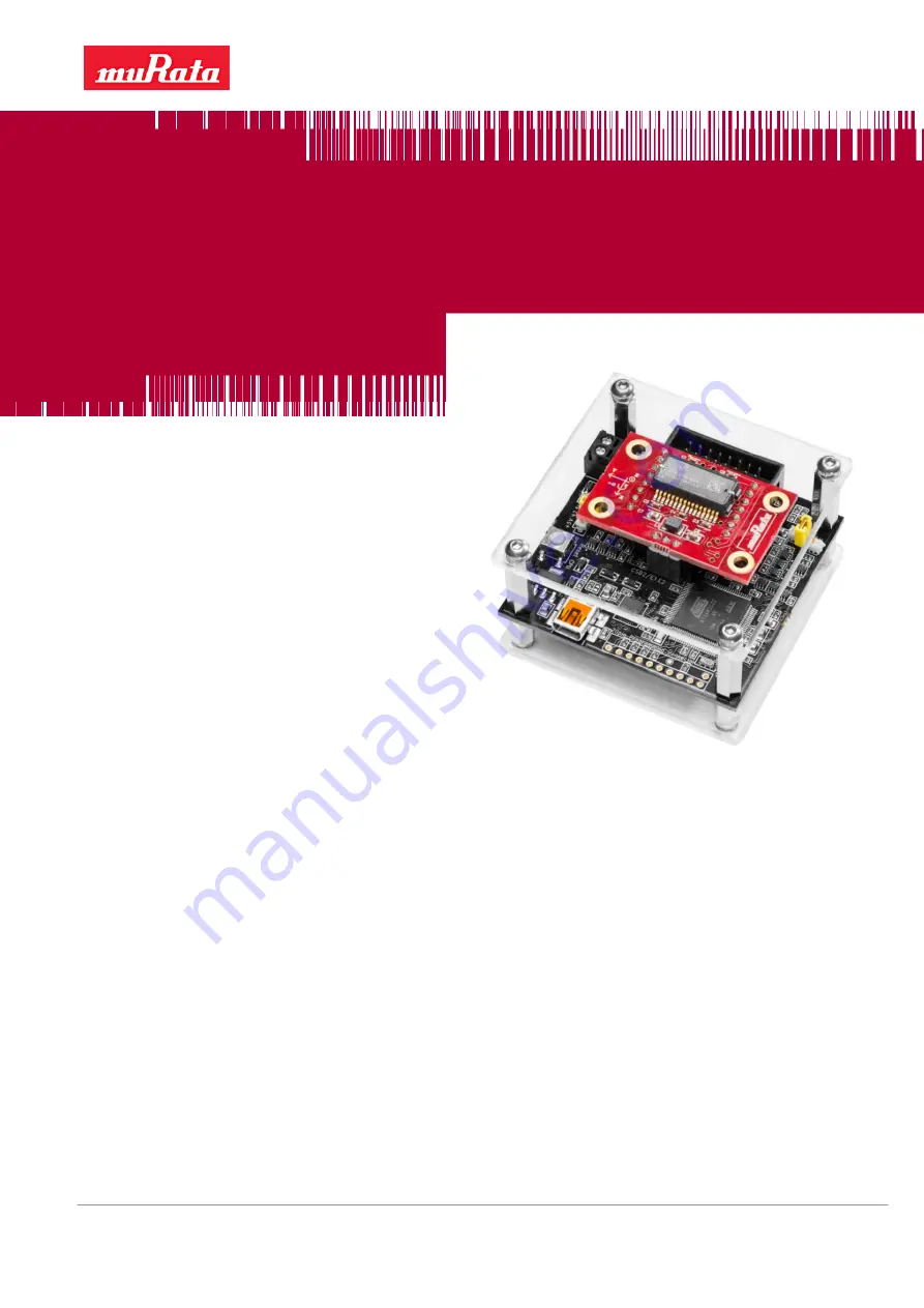
Murata MEMS Evaluation
Unit User Manual
Murata Electronics Oy
Subject to changes
1/34
www.murata.com
Doc.Nr. 82175700
Rev.D
Murata MEMS Evaluation Unit User Manual
Page 1: ...Murata MEMS Evaluation Unit User Manual Murata Electronics Oy Subject to changes 1 34 www murata com Doc Nr 82175700 Rev D Murata MEMS Evaluation Unit User Manual...
Page 2: ...Reset demo system 12 5 3 9 Changing moving average filter sample count 12 5 3 10 Read all status registers 13 5 3 11 I O pin control 13 5 4 Accelerometer view 14 5 4 1 Output data values 14 5 4 2 Sen...
Page 3: ...ommands view 27 6 7 Cannot check the syntax for macro command 27 6 8 Wrong output values or axis directions 27 6 9 Installing Java 27 6 10 Installing FTDI drivers 27 7 Uninstalling the GUI and FTDI dr...
Page 4: ...version please check for updates on page http www murata com en eu products sensor accel demokit 2 Quick start for using the Murata MEMS Evaluation Unit Please follow the steps below 1 Insert the acco...
Page 5: ...nsors an additional external power supply from 7 to 15 VDC is needed The external power can be connected to the screw terminals on the MEMS evaluation board or on the extension board The USB cable is...
Page 6: ...MEMS demo folder also contains an icon for the shortcut AppIcon ico This can be set for the shortcut by right clicking the created shortcut on the desktop and selecting Properties Change Icon and the...
Page 7: ...an be used to select the evaluation board and sensor types and open the connection to the board To start the demo GUI Select the connection type USB or Virtual COM port VCP Select the evaluation board...
Page 8: ...itial setup view after selecting an SCA3100 sensor If more than one USB device is connected all devices will be listed in the Select demo board ID field If the user does not know the ID of the board p...
Page 9: ...ues are stored to an initialization file and they are reloaded automatically during the next start up except the controls Zero offsets and Save output data to file Figure 5 Setup view 5 3 1 Operation...
Page 10: ...cleared The next received output data samples are then used as offset values for any subsequent data samples 5 3 4 Data rate The Data rate control is used to change the rate at which the output data...
Page 11: ...sensor and data format raw vs decimal The data file starts with a file header containing information on the time and date the GUI version and various GUI parameter values Comment lines start with the...
Page 12: ...hed the operation mode is set and the measurement macro to read output data is reloaded and executed Figure 13 Button to restart data collection 5 3 9 Changing moving average filter sample count It is...
Page 13: ...ters to their initial values 5 3 11 I O pin control The Murata MEMS demo can wait for an external trigger input before reading the output data Figure 16 shows the controls for I O pin configuration Th...
Page 14: ...ion if enabled in Setup view and possibly a resultant value The resultant is calculated according to the following formula Resultant 2 2 2 z y x The output data view also shows indicators for the data...
Page 15: ...redefined sensor specific ranges as well as Automatic and Manual modes The Automatic mode scales the chart range according to the minimum and maximum values shown on the chart Use the Manual mode to s...
Page 16: ...4 5 Zooming the chart The chart cannot be updated while zooming so the user must first freeze the chart then the left mouse button can be used to zoom the chart After zooming the GUI shows data marker...
Page 17: ...ate Samples second The Data rate control in the Setup view can be used to change the rate If the difference between the Data rate control value and the resulting data rate value is greater than 5 the...
Page 18: ...s the differential measurement mode the numerical indicators Differential output g are shown If the sensor has separate X and Y axes the numerical indicators OUT x are shown to indicate acceleration a...
Page 19: ...to Moving average sample count in section 5 3 9 If Read power supply voltage is enabled the GUI will receive a supply voltage value for every measurement data sample This value is used to scale the o...
Page 20: ...ensor and data to write to the sensor The user must select the memory and register from the drop down menus The view will read the register automatically when the register is selected from the menu Th...
Page 21: ...able saving all responses to a file The Delete all macros button can be used to clear all macros from the MEMS evaluation board memory Figure 30 View for sending macro commands The macro command parse...
Page 22: ...section for more information on how to benefit from this feature The Restart collecting data button will send a macro to read output values from the selected sensor Use this button after sending comma...
Page 23: ...ion If the Change sensor type menu item is selected the view shown in Figure 3 will be shown for the user Figure 34 File menu The Help menu contains items to show online sensor information the user ma...
Page 24: ...ad output and store the output values to a file the Macro commands view can be used First send a command to read specific sensor registers and then select the Store responses to file check box which w...
Page 25: ...n Java is not installed or not in the PATH environment variable If the USB library was not found the GUI will show the following error message and exit Check the error message or the log file under th...
Page 26: ...s not shown please check the following Make sure chart updating is enabled i e check Freeze chart Update chart button If chart updating is enabled use the Reset system button in the Setup view to rest...
Page 27: ...ine JRE must be installed Usually this is already the case but if the JRE is not installed download the installation package from Java s website http www java com en download index jsp execute the ins...
Page 28: ...0 Rev D Linux users should read Installing the D2XX shared library and static library section from the Drivers FTDI Linux ReadMe txt file for instructions on how to install FTDI D2XX drivers to the Li...
Page 29: ...Manager and search for the USB Serial Converter device under the Universal Serial Bus controllers devices list then right click the device and select Uninstall to uninstall the driver The figure belo...
Page 30: ...left corner when the USB connector is at the bottom The numbering runs counter clockwise Figure 45 Chip carrier pin numbering Table 1 Chip carrier connector pin descriptions PIN Description Position 1...
Page 31: ...dditionally it also has the power supply inputs from the base board This makes it possible to power the evaluation board through the external board if necessary Table 2 External board connector pin de...
Page 32: ...ed There is an External Vcc connector on the evaluation board or the external power can be provided through the 16 pin external board connector The external power supply voltage range is from 7V to 15...
Page 33: ...hat with just the USB supply the 5V supply voltage option cannot be used instead an external 5V power supply is needed The reason for this is that the USB voltage level seldom is more than 5V and usua...
Page 34: ...hift is done to support 2 5V and 3 3V supply voltages The full range of I2C is from 1 8V to 3 6V Table 4 SN74LVC1T45 electrical characteristics DVIO MIN MAX UNIT VIH High level input voltage 1 65 V to...