background image

ENC-03J type

4

5. Installation

1) Install the sensor by using the bottom face as the reference point.

2) Install the sensor vertically with respect to the rotating surface. (90 +/- 5 deg )

3) Install the sensor in a location which minimizes excessive vibration (ex. Model helicopter

application) and use elastic materials to absorb external shock and vibration.

Typically, the sensor can withstand vibration that frequency 10~55Hz, amplitude 1.5mmp-p,

duration 2hours.

4) Install the sensor in a place which minimizes substantial temperature variations.

5) When installing the sensor, terminals should be hand soldered onto the PCB.

Observe the following guideline, otherwise, characteristics may vary due to excessive soldering

heat:

      320 +/- 10deg C, 2s or less.

    6) Do not bend terminals.

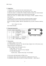
6. Terminal connection

Terminal

Symbols

Descriptions

1

+Vcc

Supply voltage

[input]

2

Vref

Comparative

voltage(approx

.+1.35V)

[output]

3

GND

Ground

[common]

4

OUT

Sensor output

[output]

7. Connection

1) Operation voltage is +2.7V to +5.5V.

Use a stabilized power supply free from surge and ripple voltages. Also, Confirm proper power

supply polarity before connecting sensor.

2) Output voltage is relative to the angular velocity.

Output voltage = V0 + Sv x 

ω

 [V]

V0 :Static output [V]    (at angular velocity is 0 [deg/s])

Sv :Scale factor [mV/deg/s]

 : Angular velocity    [angular velocity range : -90 to +90 deg/s]

3) Use a sensor output load resistance of 50k

 or more.

4) Comparative voltage (Vref) must be grounded with condenser of 4.7µF or more.

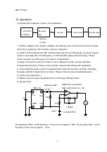
5) Comparative voltage is used as a reference voltage of amplification.    (Refer to page 7)

B O T T O M   V I W E

Summary of Contents for GYROSTAR ENC-03JA

Page 1: ...ANUAL OF GYROSTAR Piezoelectric vibrating Gyroscope MODEL ENC 03J TYPE Support sensor for video camera May 6 1999 PRODUCT ENGINEERING SECTION SENSOR MODULE DEPERTMENT CIRCUIT PRODUCTS DIVISION MURATA...

Page 2: ...ifies equipment structure and circuit configuration thus making it possible to provide outstanding performance This sensor can be used for positional control and posture control of a moving object req...

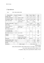
Page 3: ...oefficient of scale factor Reference Ta at 5 75 C 20 10 FS Resonance frequency version ENC 03JA version ENC 03JB fa fb 22 24 kHz kHz Resonance frequency disparity fa fb at 5 75 C 1 kHz Linearity in th...

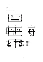
Page 4: ...ENC 03J type 3 4 Dimensions All dimensions are in mm Measurement tolerance 0 2mm 2 25 1 5 15 24 3 2 1 0 4 1 4 3 15 44 03JA M JPN 841 0 6 3 81 Vcc 1 Out Vref G n d 3 4 2 8 0...

Page 5: ...ue to excessive soldering heat 320 10deg C 2s or less 6 Do not bend terminals 6 Terminal connection Terminal Symbols Descriptions 1 Vcc Supply voltage input 2 Vref Comparative voltage approx 1 35V out...

Page 6: ...on of the resonant frequencies By using different frequencies mutual interference can be avoided When detecting just one axis select model ENC 03JA When detecting two axes select models ENC 03JA and E...

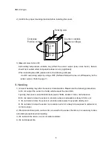
Page 7: ...correct handling may affect the sensor characteristics Please note the following precautions A Do not subject the sensor to shocks which exceed the rated limit Typically the sensor can withstand shock...

Page 8: ...e application 3 Always use an A D converter of 8 bits or more Resolution of A D converter will affect measurement accuracy Please choose a proper resolution according to the application 4 The sampling...

Page 9: ...signal equipment 7 Disaster prevention crime prevention equipment 8 Data processing equipment 9 Applications of similar complexity or with reliability requirements comparable to the applications liste...

Reviews:

Related manuals for GYROSTAR ENC-03JA