
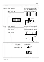
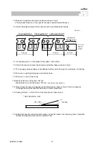
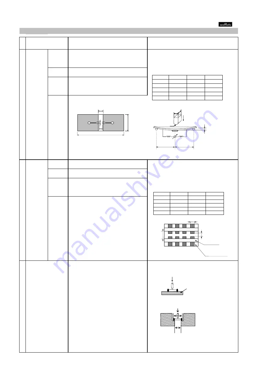
18 Board Flex
Appearance
No marking defects
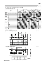
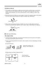
Solder the capacitor on the test jig (glass epoxy board) shown in
Fig1 using a eutectic solder. Then apply a force in the direction
shown in Fig 2 for 5
±
1sec. The soldering should be done by the
reflow method and should be conducted with care so that the
Capacitance
C7: Within ±10.0%
soldering is uniform and free of defects such as heat shock.
Change
Dissipation
C7: 0.1max
Factor
Insulation
50
Ω
・F
min.
Resistance
(in mm)
19 Terminal
Appearance
No marking defects
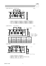
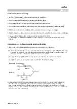
Solder the capacitor to the test jig (glass epoxy board) shown in
Strength
Fig.3 using a eutectic solder. Then apply *18N force in parallel with
Capacitance
Within specified tolerance
the test jig for 60sec.
Change
The soldering should be done either with an iron or using the reflow
Dissipation
C7: 0.1max
method and should be conducted with care so that the soldering is
Factor
uniform and gree of defects such as heat shock
*2N(GCM15)
Insulation
50
Ω
・
F min.
Resistance
(in mm)
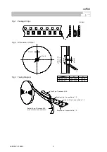
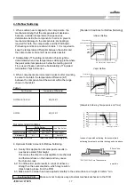
20 Beam Load Test
Destruction value should be exceed following one.
Place the capacitor in the beam load fixture as Fig 4.
< Chip L dimension : 2.5mm max. >
Apply a force.
< Chip Length : 2.5mm max. >
< Chip L dimension : 3.2mm max. >
< Chip Length : 3.2mm min. >
Speed supplied the Stress Load : 0.5mm / sec.
Chip thickness
≧
1.25mm rank : 54.5N
Chip thickness > 0.5mm rank : 20N
Chip thickness
≦
0.5mm rank : 8N
■
AEC-Q200 Murata Standard Specification and Test Methods
No
AEC-Q200 Test Item
AEC-Q200 Test Method
Specification.
Chip thickness < 1.25mm rank : 15N
t : 1.6mm
Fig.4
(GCM15:0.8mm)
Type
a
b
c
GCM15
0.5
1.5
0.6
GCM18
0.6
2.2
0.9
GCM21
0.8
3.0
1.3
GCM31
2.0
4.4
1.7
GCM32
2.0
4.4
2.6
*2
4.0±0.1
8.
0±
0.
3
3.5
±
0.
05
0.05以下
*1
φ1.5
+0.1
-0
A
t
*1,2:2.0±0.05
1.75
±
0.
1
B
100
40
a
c
b
C
Fig.1
Type
a
b
c
GCM15
0.4
1.5
0.5
GCM18
1.0
3.0
1.2
GCM21
1.2
4.0
1.65
GCM31
2.2
5.0
2.0
GCM32
2.2
5.0
2.9
*2
4.0±0.1
8
.0
±
0.
3
3.5
±
0
.0
5
0.05以下
*1
φ1.5
+0.1
-0
A
t
*1,2:2.0±0.05
1.75
±
0.
1
B
a
a
c
b
ランド
f
4.5
c
Solder resist
Baked electrode or
Copper foil
b
T:1.6mm
(GCM15:0.8mm)
Fig.3
Iron Board
L
0.6L
45
45
Flexure:≦2
(High Dielectric Type)
Capacitance meter
Pressurizing
speed:1.0mm/s
Pressurize
支持台
コンデンサ
45
45
Fig.2
R4
20
114
JEMCGS-02374
5