
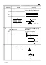
14 Thermal Shock
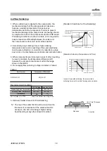
The measured and observed characteristics shall satisfy the
Fix the capacitor to the supporting jig in the same manner and under
specifications in the following table.
the same conditions as (19). Perform the 300 cycles according to
Appearance
No marking defects
the two heat treatments listed in the following table(Maximum
Capacitance
C7: Within ±10.0%
transfer time is 20 seconds). Set for 24±2 hours at room
Change
temperature, then measure
Dissipation
C7: 0.1max
Factor
Insulation
50
Ω
・
F min.
Resistance
・
Initial measurement for high dielectric constant type
Perform a heat treatment at 150+0/-10
℃
for one hour and then set
for 24±2 hours at room temperature.
Perform the initial measurement.
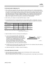
15 ESD
Appearance
No marking defects
Per AEC-Q200-002
Capacitance
Within the specified tolerance
Change
Dissipation
C7: 0.1max
Factor
Insulation
50
Ω
・
F min.
Resistance
16 Solderability
(a) Preheat at 155
℃
for 4 hours. After preheating, immerse the
capacitor in a solution of ethanol(JIS-K-8101) and rosin (JIS-K-
5902) (25% rosin in weight propotion). Immerse in
eutectic solder solution for 5+0/-0.5 seconds at 235±5
℃
.
(b) Should be placed into steam aging for 8 hours±15 minutes.
After preheating, immerse the capacitor in a solution of
ethanol(JIS-K-8101) and rosin (JIS-K-5902) (25% rosin in weight
propotion). Immerse in eutectic solder solution for 5+0/-0.5
seconds at 235±5
℃
.
(c) Should be placed into steam aging for 8 hours±15 minutes.
After preheating, immerse the capacitor in a solution of
ethanol(JIS-K-8101) and rosin (JIS-K-5902) (25% rosin in weight
propotion). Immerse in eutectic solder solution for 120±5
seconds at 260±5
℃
.
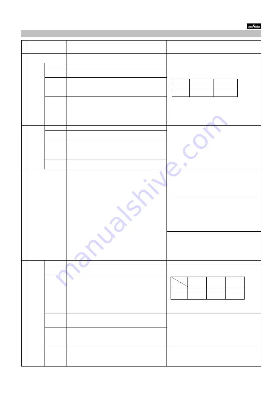
17 Electrical
Appearance
No defects or abnormalities
Visual inspection.
Chatacteri-
Capacitance
Within the specified tolerance
The capacitance/Q/D.F. should be measured at 25
℃
at the
zation
Change
frequency and voltage shown in the table.
Dissipation
C7 :0.1max
Factor
Insulation
50
Ω
・
F min.
The insulation resistance should be measured with a DC voltage not
Resistance
exceeding the rated voltage at 25
℃
and 125
℃
within 1 minute of
25
℃
charging.
Insulation
5
Ω
・
F min.
Resistance
125
℃
150
℃
Dielectric
No failure
No failure should be observed when 250% of the rated voltage is
Strength
applied between the terminations for 1 to 5 seconds, provided the
charge/ discharge current is less than 50mA.
95% of the terminations is to be soldered evenly and continuously.
■
AEC-Q200 Murata Standard Specification and Test Methods
No
AEC-Q200 Test Item
AEC-Q200 Test Method
Specification.
Step
1
2
Temp.(
℃
)
-55+0/-3
125+3/-0
Time (min.)
15±3
15±3
Char.
Item
C7
6.3V max.
(C
≦
10
F)
C7
10V min.
(C
≦
10
F)
C7
(10
F < C)
Frequency
1
0.1kHz
1
0.1kHz
120
24Hz
Voltage
0.5
0.1Vrms
1
0.2Vrms
0.5
0.1Vrms
JEMCGS-02374
4


