background image

28

=

 For details about how to use manifold valves, see the

instruction manual for manifold valves.

=

 The handle Hi below connect operate during the following

work if it is fully closed.

=

 Evacuate every indoor unit for rooms A

B and C.

Air purge and leak test

In the case of gas leakage

Tighten the flare nut connections.

If this tightening does not help stopping the leakage

repair the leak portion (s).remove the gas from the

service port, refill the specified amount from the

cylinder gas.

WARNING:

When installing or moving the unit, do not mix

anything other than specified refrigerant (R22) into

the refrigerating cycle.

If air is mixed,it may cause the refrigerating cycle to

get abnormally high temperatre, causing a risk of

burst.

Evacuate the circuit for 15 minutes or more,and make sure
that the compound pressure gage reads-760 mm Hg.

After finishing the evacuation.fully close the handle Lo on
the manifold valve. and then stop the vacuum pump.

Fully  open the stop valve (2-way and 3-way valves) by
turning the valve rods to the left until they stop When the
rods contact the stoppers. do not apply force any more.

Tighten the valve rod caps for the stop valves (2-way and
3-way valves).

Leak test
Using soapy water. perform the leak test for both the indoor
and outdoor sides,Make sure no bubbles appear on the
connections. If bubbles appear they indicate gas is leaking
from that point.

If gas is leaking
Tighten the flare nut connection more strongly.
If it has no effect.repair any existing leak points,release all
gas from the service port completely,and then recharge the
specified amount of refrigerant gas from cylinder.

Make sure the pipes have been connected properly.

Connect the manifod valve to the service port of the stop
valve (3- way valve) by using a charge hose.At this time,
the inside-core end of the charge hose must be connected
to the service port.

Make sure the stop valve (2-way and 3-way valve) are fully
closed. and then connect another charge hose to a vacuum
pump.

Fully open the handle Lo on the manifold valve, and then
run the vacuum pump.
Loosen the flare nut of the stop valve (3-way valve) slightly
to make sure that air is entering it.
Then, retighten the flare nut.
(If air is not entering it, make sure again the charge hose is
fimly connected to the service port.)

Cap for service port

Cap for stop valve

N.m

13.7 to 17.7

19.6 to 29.4

kgf.cm

140 to 180

200 to 300

Tightening torque

Mite

Pressar gage

Hande Hi

Charge
bose

Hande Lo

Comperad powere gage

Summary of Contents for MUP-12+062X2C

Page 1: ...MUND CLIMA Series 2000 Multisplit 3x1 User s Manual COOL ONLY MUP 12 062X2C...

Page 2: ...d tightly Otherwise it can cause an electric shock overheating or fire WARNING Don t apply the cold wind to the body for a long time It cause the physical condition deferioration and health problems W...

Page 3: ...stop driving and turn off the power suply It occasionally cause the electric shock Don t block the air intake or outlet vents of both the outdoor and indoor units It can decrease the air cond itioning...

Page 4: ...d function of each part Operation indicator GREEN light up when the unit is on and flashing when the unit is defrosting Air in SET TEMP RUN SIGNAL RECEPTOP Air out Air out STOP 2 3 Air in 1 4 6 7 8 5...

Page 5: ...matically and stop when repressed TEMP button SETTEMP increases 1 by pressing button once and decreases 1 by pressing button once At COOL mode operation SET TEMP can be selected from 16 to 30 At DRYmo...

Page 6: ...stopping press TIMER ON button set ON TIME in range of 0 to 24 hour to start the unit automatically SWING FAN SLEEP MODE 1 0 AIR HUMID LIGHT TIMER ON TIMER OFF ANION SAVE SWING HUMID LIGHT SAVE AUTO A...

Page 7: ...ress SWING button the louvers start to ro tate automatically and stop when repress 1 Plug in press 1 0 button then air conditioner is turned on According to difference between room temp and set temp m...

Page 8: ...han set temp it s at COOL mode SET TEMP should be in range of 16 to 30 K K K K K 3 Press SWING button the louvers start to ro tate automatically and stop when repress it 4 Press TEMP button set suitab...

Page 9: ...2 According to room temp micro computer can automatically set operation mode so as for best effect 1 Plug in Press 1 0 button then air conditioner is turned on SWING FAN SLEEP MODE 1 0 AIR HUMID LIGHT...

Page 10: ...ON TIME in range of 0 to 24 hour to start the unit automatically At operating press TIMER OFF button set OFF TIME in range of 0 to 24 hour to stop the unit automatically SWING FAN SLEEP MODE 1 0 AIR H...

Page 11: ...tomatically and stop when repress 6 SLEEP button Press it to set SLEEP operation SWING FAN SLEEP MODE 1 0 AIR HUMID LIGHT TIMER ON TIMER OFF ANION SAVE SWING AUTO FAN OPER When the unit is cooling or...

Page 12: ...emote control 2 Insert the two batteries Two AAA dry cell batteries and press button ACL 3 Re attach the cover NOTE Don t confuse the new and worn or different batteries Remove batteries when not in u...

Page 13: ...ise compressor would vibrate terribly to damage refrigeration system Don t blow the wind to animals and plants directly It can cause a bad influence to them The ground must be connected Don t connect...

Page 14: ...o clean the dust adhering to the filters you can either use a vacuum cleaner or wash them with water and dry it in the shade NOTE Never use water above 45 to wash the filters or it could cause deforma...

Page 15: ...ters and other parts 2 Turn main power off 3 Clean dust from the outdoor unit 4 Repaint the rubiginous place on the outdoor unit to prevent it from spreading Replacement of Air cleaner Recommended onc...

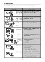
Page 16: ...d when start or stop the unit Air conditioner does not operate at all Cooling efficiency is not good Once the air conditioner is stopped it will not operate in approximately 3 minutes to protect itsel...

Page 17: ...h service center Unusual noise can be heard during operation Power fuse or switch often breaks Carelessly splash water or something into air conditioner Electrical lines and power plug are very hot Wi...

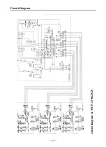
Page 18: ...17 Circuit Diagram circuit diagram of MUP 12 062X2C...

Page 19: ...apping tape Connection piping Thermal insulation hose Air cleaner Plastic square ring Diagram specification 7 1 5V 4G 1 0 ST4 2 25 L 2m 120 65 25 30 10 6 9 5 35 500 Memo Fix the rear panel Qty N N O N...

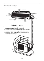
Page 20: ...nstallation When picking up and moving the units you must be guided by trained and qualified personnel Installation dimension diagram 3 0 c m o r m o r e Space to the wall Air outlet side 15cm or more...

Page 21: ...at the distance from the location to the ground is more than 2 3m Outdoor unit 1 Select location from which noise and outflow air emitted by unit will not inconvenience neighbors 2 Select location whe...

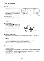
Page 22: ...ing from being damaged when passing through the hole Electrical wiring 1 Open the surface panel 2 Remove the wiring cover 3 Route the power connection cord from the back of the indoor unit and pull it...

Page 23: ...installed location should be 2 3m or more from the floor NOTE All the electrical work must be done by qualified personnel according to the local rules and this manual The rated voltage and the exclus...

Page 24: ...nstallation manual If there is some deficiency in draining and pinping work it may cause a risk of dripping from the unit wetting or fouling your property How to remove the service panel Remove the fo...

Page 25: ...4G1 0 Outdoor unit 220 230V 25A 3 2 5 CAUTION Be careful not to make mis wiring Firmly tighten the terminal screws to prevent them from loosening After tightening pull the wires lightly to confirm th...

Page 26: ...o be added No additional charge 10 g m A unit B unit Indoor unit A and B or C are in the same refrigerant cycle system so please add enough refrigerant to run both units Aand B or C Piping preparation...

Page 27: ...Flaring work Perform flaring work using flaring tool as shown in the right Firmly hold copper pipe in a die in the dimension shown in the table above 5 Check Compare the flared work with figure in th...

Page 28: ...unit For tightening use the same tightening torque applied for indoor unit and tig then the flare nut with torque wrench or spanner Insulation and taping Cover piping joints with pipe cover For outdo...

Page 29: ...aps for the stop valves 2 way and 3 way valves Leak test Using soapy water perform the leak test for both the indoor and outdoor sides Make sure no bubbles appear on the connections If bubbles appear...

Page 30: ...stallstion plate When releasing the corner part Release both left and right bottom corner part of indoor unit and pull it downward and forward as shown toto release the hooks If the above method canno...

Page 31: ...ge liquid refrigerant such as by inverting the gas cylinder while charging otherwise troubles may be generated To maintain the high pressure of the gas cylinder warm the gas cylinder with warm water u...

Page 32: ...AUTO mode operation procedure TIMER mode operation procedure SLEEP mode operation procedure HOW to insert batteries User notices Care and Maintenance Troubleshooting Circuit diagram Accessories and i...

Reviews: