Munchkin Gas-Fired Hot Water Boiler Manual Download Page 22

21

GAS-FIRED BOILER 

Boiler Manual

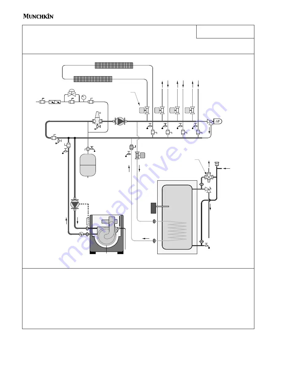
Standard Munchkin boiler
Preferred piping (zoning with valves)

Space heating mode

Munchkin boiler

P1

Super Stor

indirect DHW tank

T/P

Drawing 2A

make-up water

zone valves

NOTES:

1.  

This drawing is meant to show system piping concept only.  
Installer is responsible for all equipment & detailing required by local codes.

2.  

Adjust differential pressure bypass valve to eliminate any flow velocity noise when zone with highest pressure 
drop operates by itself.

3.  

The minimum pipe size for connecting a Super Stor water heater is 1 inch.

4.  

The minimum pipe size for connecting a Munchkin boiler is 1.25 inches and 2 inches for the 399M.

5.  

All pumps are shown with isolation flanges.  The alternative is standard flanges with full port ball valves. 

6.  

The anti-scald mixing valve is recommended if the DHW temperature is set above the factory setting of 119˚F.

7.

Install a minimum of 12 diameters of straight pipe upstream of all circulators.

8.

A purging valve may be used in lieu of the ball valve / hose bib combination shown.

9.

A minimum of 6 pipe diameters of straight pipe shall be installed upstream and downstream 
of all closely spaced tees.

V1

differential
pressure
bypass
valve

anti-scald

mixing valve

purging

valves

closely

spaced

tees

P2

cold

water

OFF

NOTE: For Vision piping applications, refer to the Vision Installation Piping Diagrams.

Summary of Contents for Gas-Fired Hot Water Boiler

Page 1: ...nstaller service technician Read all instructions in this manual before installing Perform steps in the order given Failure to comply could result in severe personal injury death or substantial proper...

Page 2: ...ff D Backflow Preventer E System Water Piping Methods F Circulators G Hydronic Piping with Circulators Zone Valves and Multiple Boilers H Circulator Sizing WARNING If the information in this manual is...

Page 3: ...Exhaust Vent and Intake Air Vent Pipe Location E Exhaust Vent and Intake Air Vent Sizing G Exhaust Vent and Intake Air Pipe Installation H Heater Removal from a Common Vent System I Condensate Remova...

Page 4: ...ption 57 60 A Programming the Vision I Option B Vision I Program Access C Vision I Program Navigation Part 14 Trouble Shooting 61 63 A Munchkin Error Code B Boiler Error C Boiler Fault Part 15 Mainten...

Page 5: ...symbol indicates a potentially hazardous situation which if not avoided may result in property damage DEFINITIONS NOTICE Heat Transfer Products Inc reserves the right to make product changes or update...

Page 6: ...at exchanger reduces heat transfer overheats the stainless steel heat exchanger and causes failure Addition of oxygen carried in by make up water can cause internal corrosion in system components Leak...

Page 7: ...savings 3 Gas Valve The gas valve senses suction from the blower allowing gas to flow only if the gas valve is powered and combustion air is flowing 4 Supply water temperature sensor This sensor monit...

Page 8: ...eezing temperatures or any other type of blockage Plastic tubing must be the only material used for the condensate line Steel brass copper or others will be subject to corrosion or deterioration A sec...

Page 9: ...the condensate to flow to the location of the condensate hose the boiler must be slightly pitched back to assure proper flow direction The Munchkin Boiler comes equipped with leveling feet Should you...

Page 10: ...1 4 NPT 3 4 2 4250 1200 58 lbs 80M 27 000 80 000 74 000 64 000 95 1 0 8 gal 1 1 4 NPT 3 4 3 3700 1600 75 lbs 140M 46 000 140 000 129 000 112 000 95 1 1 4 gal 1 1 4 NPT 3 4 3 3550 1400 101 lbs 199M 66...

Page 11: ...10 GAS FIRED BOILER Boiler Manual DIMENSIONS 80M 140M 199M Figure 2 2 Figure 2 3...

Page 12: ...ordinances National Fuel Gas Code ANSI Z223 1 latest edition Standard for Controls and Safety Devices for Automatically Fired Boilers ANSI ASME CSD 1 when required National Electrical Code For Canada...

Page 13: ...VENT The Munchkin Boiler requires a special vent sys tem designed for pressurized venting Munchkin Boilers are rated ANSI Z21 13 Category IV pressurized vent likely to con dense in the vent You must...

Page 14: ...nce will operate continuously e Test for spillage at draft hood opening after 5 PART 3 PREPARE BOILER LOCATION CONTINUED DANGER Do not install the Munchkin Boiler into a common vent with any other app...

Page 15: ...lief valve to operate resulting in possibility of severe personal injury death or substantial property damage minutes of main burner operation Use the flame of a match or candle or smoke from a cigare...

Page 16: ...nsion tank 1 Always install an automatic air vent on top of the air separator to remove residual air from the system F CIRCULATORS Sizing space heat system piping 1 See Piping Details in this manual P...

Page 17: ...the cooling cycle Chilled Water Medium must be piped in parallel with the heater Freeze Protection for new or existing systems must use glycol that is specifically formulated for this purpose It will...

Page 18: ...14 16 18 20 22 24 26 28 30 32 5 10 15 20 25 30 35 37 5 40 Flow in Gallons per Minute Friction in Feet of Head MUNCHKIN 399M NOTE The recommended circulators are based on 1 gpm per 10 000 btu hr with...

Page 19: ...in volume for a temperature increase from 32 F to 180 F while water expands 3 with the same temperature rise Allowances must be made for this expansion in the system design 4 A 30 mixture of glycol w...

Page 20: ...supply only the boiler loop 2 Install a separate circulator for each zone 3 Connect DHW domestic hot water piping to indirect storage water heater as shown L MULTIPLE BOILERS 1 Connect multiple boile...

Page 21: ...way valve zone valve air separator backflow preventer diaphragm type expansion tank pressure reducing valve diff pressure bypass anti scald rated mixing valve pressure gauge 4 way motorized mixing va...

Page 22: ...ze for connecting a Munchkin boiler is 1 25 inches and 2 inches for the 399M 5 All pumps are shown with isolation flanges The alternative is standard flanges with full port ball valves 6 The anti scal...

Page 23: ...lf 3 The minimum pipe size for connecting a Super Stor water heater is 1 inch 4 The minimum pipe size for connecting a Munchkin boiler is 1 25 inches and 2 inches for the 399M 5 All pumps are shown wi...

Page 24: ...pipe size for connecting a Munchkin boiler shall be 1 25 inches and 2 inches for the 399M 6 All pumps are shown with isolation flanges The alternative is standard flanges with full port ball valves 7...

Page 25: ...installed upstream and downstream of all closely spaced tees 4 The minimum pipe size for connecting a Super Stor water heater is 1 inch 5 The minimum pipe size for connecting a Munchkin boiler shall...

Page 26: ...e size for connecting a Munchkin boiler shall be 1 25 inches and 2 inches for the 399M 6 All pumps are shown with isolation flanges The alternative is standard flanges with full port ball valves 7 The...

Page 27: ...pipe size for connecting a Munchkin boiler shall be 1 25 inches and 2 inches for the 399M 6 All pumps are shown with isolation flanges The alternative is standard flanges with full port ball valves 7...

Page 28: ...n tained B ZONING WITH ZONE VALVES USING VISION I 1 Connect the boiler to the system as shown in piping details 3A through 3C 2 Connect the DHW circulator P2 directly to the boiler as shown as shown i...

Page 29: ...99M 6 All pumps are shown with isolation flanges and integral flow check valves The alternative is standard flanges with full port ball valves and a separate flow check valve 7 The anti scald mixing v...

Page 30: ...own with isolation flanges and integral flow check valves The alternative is standard flanges with full port ball valves and a separate flow check valve 7 The anti scald mixing valve is recommended if...

Page 31: ...es with full port ball valves and a separate flow check valve 7 The anti scald mixing valve is recommended if the DHW temperature is set above the factory setting of 119 F 8 Install a minimum of 12 di...

Page 32: ...r shall be 1 25 inches and 2 inches for the 399M 6 All pumps are shown with isolation flanges and integral flow check valves The alternative is standard flanges with full port ball valves and a separa...

Page 33: ...boiler shall be 1 25 inches and 2 inches for the 399M 6 All pumps are shown with isolation flanges and integral flow check valves The alternative is standard flanges with full port ball valves and a...

Page 34: ...n with isolation flanges and integral flow check valves The alternative is standard flanges with full port ball valves and a separate flow check valve 7 The anti scald mixing valve is recommended if t...

Page 35: ...n flanges and integral flow check valves The alternative is standard flanges with full port ball valves and a separate flow check valve 7 The anti scald mixing valve is recommended if the DHW temperat...

Page 36: ...ral flow check valves The alternative is standard flanges with full port ball valves and a separate flow check valve 7 The anti scald mixing valve is recommended if the DHW temperature is set above th...

Page 37: ...pipe size for connecting a Super Stor water heater is 1 inch 5 The minimum pipe size for connecting a Munchkin boiler shall be 1 25 inches and 2 inches for the 399M 6 All pumps are shown with isolatio...

Page 38: ...alternative is standard flanges with full port ball valves and a separate flow check valve 7 The anti scald mixing valve is recommended if the DHW temperature is set above the factory setting of 119 F...

Page 39: ...art 7 Ensure the exhaust and intake piping comply with these instructions regarding vent system Inspect finished combustion air intake and exhaust piping thoroughly to ensure all joints are well secur...

Page 40: ...ance or hazard h When adjacent to a public walkway locate exit terminal at least 7 feet above grade i Do not locate the exhaust directly under roof overhangs to prevent icicles from forming j Provide...

Page 41: ...and direct vent venting systems Reference National Fuel Gas Code ANSI Z223 1 NFPA 54 2002 Fig 7 3 Multiple Vent Spacing Note Exhaust must extend out 1 foot Figure 7 5 Multiple Boiler Installations Fig...

Page 42: ...bined equivalent length is 16 equivalent feet F LONGER VENT RUNS 1 The maximum combined equivalent length can be extended by increasing the diameter of both exhaust vent and intake air vent pipe equal...

Page 43: ...between the space in which the appliance remains connected to the common venting system located and other spaces in the building Turn on clothes dryers and any appliances not connected to the common...

Page 44: ...he condensation line may be necessary to avoid blockage of the conden sate flow CAUTION The condensate line must remain unobstructed allowing free flow of condensate If condensate is allowed to freeze...

Page 45: ...IDEWALL VENTING WITH TEE INTAKE AND COUPLING EXHAUST COUPLING EXHAUST INTAKE AIR VENT 12 MIN EXTERIOR WALL TEE ALL HORIZONTAL TOP VIEW STRAIGHT AND VERTICAL PIPING COUPLING SUPPORT BRACKETS MUST BE US...

Page 46: ...PIPING ALL HORIZONTAL EXTERIOR WALL VENT EXHAUST RIGHT SIDE VIEW MUST BE FACING UP NOTE INTAKE LEG SUPPORT BRACKETS MUST BE USED ON INTAKE AIR VENT 1 MIN AND VERTICAL PIPING FRONT VIEW EXTERIOR WALL M...

Page 47: ...R 12 OVER MAXIMUM SNOW LEVEL OR 24 10 0 MIN RIGHT SIDE VIEW EXTERIOR WALL INTAKE AIR VENT ROOF VENT WITH CONCENTRIC VENT KIT AND VERTICAL PIPING ALL HORIZONTAL SUPPORT BRACKETS MUST BE USED ON EXHAUST...

Page 48: ...esent The gas piping must be sized for the proper flow and length of pipe to avoid pressure drop Both the gas meter and the gas regulator must be properly sized for the total gas load If you experienc...

Page 49: ...12 FIGURE 12 1 Fig 8 2 service to an area to provide maintenance to their lines This gas valve must not be replaced with a conventional gas valve under any circumstances As an additional safety featur...

Page 50: ...1 Connect room thermostat or end switch 2 Install thermostat on inside wall away from influences of drafts hot or cold water pipes lighting fixtures television sunrays or fireplaces 3 Thermostat antic...

Page 51: ...50 GAS FIRED BOILER Boiler Manual PART 9 FIELD WIRING CONTINUED Fig 9 4 Fig 9 3 Fig 9 1 Fig 9 2...

Page 52: ...51 GAS FIRED BOILER Boiler Manual PART 9 FIELD WIRING CONTINUED Fig 9 5...

Page 53: ...ll allow the installer to con trol the temperature of the indirect water heater from the Munchkin Boiler and give the water heater priority over the Central Heating Circuit Once the Water Heater is sa...

Page 54: ...ufacturer s instructions B FREEZE PROTECTION WHEN USED 1 Determine freeze protection fluid quantity using total system water content following fluid manufacturer s instructions Remember to include exp...

Page 55: ...CUIT S 1 Disconnect the two external wires connected to the boiler thermostat terminals low voltage terminal strip terminals 5 and 6 2 Connect a voltmeter across these two incoming wires Close each th...

Page 56: ...t you support the condensation line to assure proper drainage H FINAL CHECKS BEFORE STARTING BOILER 1 Read Startup Procedures within this manual for proper steps to start boiler See Startup Report to...

Page 57: ...em perature setting of the Munchkin The burner will not start until the outlet water temperature reaches a temperature that is equal to the tem perature setting for the Munchkin Boiler minus the diffe...

Page 58: ...es not take place when the controller is in Test mode only temperature limitation based on the Munchkin Boiler Central Heating set point The user will be allowed to increase or decrease the fan speed...

Page 59: ...se or decrease a value you will need to press either the S 1 key or S 2 key to change the default values If there is no key action for 1 minute the display returns to normal operation Changes are effe...

Page 60: ...stalled 17 0 Interface Board Function 0 Building Management 1 Enables Tekmar Modulating control Consult with Tekmar to assure the Tekmar Control is compati ble Default Function Function Value Descript...

Page 61: ...URVE CENTRAL HEATING CURVE Factory Default 50 OUTSIDE TEMPERATURE F 59 32 41 41 24 27 9 9 0 81 45 63 99 Plot your Curve CENTRAL HEATING CURVE SUPPLY OUTLET TEMPERATURE F 167 104 77 59 68 86 95 131 113...

Page 62: ...supply to the boiler at the gas service valve Table 14 1 925 Control Board ERROR Codes WARNING When servicing or replacing any components of this boiler be certain that The gas is off All electrical...

Page 63: ...5 If there is a flame check the flame sensor 6 Check any flue blockage or condensate blocks F10 Loss of Flame Signal The boiler will relight 4 times before the control goes into this lockout condition...

Page 64: ...130 41 28600 50 22800 59 18300 68 14770 77 12000 86 9804 95 8054 104 6652 113 5522 Boiler Sensor 7250P 667 Indirect Sensor 7250P 320 Boiler and Indirect Temperature F Resistance ohms 32 32550 41 25340...

Page 65: ...thing Rinse clothes washer thoroughly NIOSH stated First Aid Eye Irrigate immediately Breathing Fresh air Munchkin Boiler side so the flow can be observed c Disconnect connections from the gas valve s...

Page 66: ...Blower 7250P 144 31 Burner Door 7250P 169 12 Combustion Blower 7250P 085 32 Burner Door Ceramic Refractory 7250P 161 13 Gas Valve Adapter Plate w Screws 7250P 644 33 Gasket Burner 7250P 070 14 Screws...

Page 67: ...play w Ribbon Cable 7250P 332 22 S S Hex Nut 10 32 Blocked Vent Pressure Switch 7250P 153 7 Blocked Vent Pressure Switch 7250P 150 23 S S Hex Nuts 7250P 559 8 Screws 8 x 1 2 Blocked Vent Pressure Swit...

Page 68: ...s Valve 7250P 718 140M 199M 7250P 117 199M 9 Swirl Plate 7500P 092 80M 26 Nut M6 Burner Door 7500P 067 7500P 093 140M 199M 27 Burner Door 7250P 684 10 Gas Valve Adapter Plate w Screws 7250P 644 28 Bur...

Page 69: ...PVC Tee Sch 40 3 4 NPT Condensate Assy 7250P 646 7 Screw 1 4 20 x 1 2 Control Board Mounting Panel 7250P 184 22 Cable Clamp Condensate Assy 7250P 649 8 Control Board Hold Down Clips 7250P 352 23 Screw...

Page 70: ...e Electrode 7250P 069 9 Screws M4 x 30MM Allen Head N A 27 Flame Rectification Probe w Gasket 7250P 049 10 Right Angle Connector 7250P 723 28 Screws Torx M5 x 22MM Air Gas Channel to Burner Door 7250P...

Page 71: ...lamp Exhaust Assembly 7250P 549 8 Fuse Control Board 7250P 378 24 PVC Pipe Sch 40 4 Exhaust Assembly 7250P 524 9 Control Board Display w Ribbon Cable 7250P 332 25 S S Hex Nut 10 32 Blocked Vent Pressu...

Page 72: ..._ppm CO Low Fire 4 Verify System Operation Turn up thermostat to verify wiring connections 5 Record Ionization Current Check A reading at d7 on the status menu see start up section ____ A High Fire __...

Page 73: ...heating curve See Part 13 Electrical Connections Check wire connections make sure they are tight Circuit breakers Check to see that the circuit breaker is clearly labeled exercise circuit breaker Swit...

Page 74: ...ECO replace if corroded Water Pressure Switch Check operation check for signs of leakage replace if corroded Thermistors Check wiring verify through ohms reading see chart part 14 Fig 14 3 Final Inspe...

Page 75: ...f installation of the side wall horizontal vented gas fueled equipment the installing plumber or gasfitter shall observe that a hard wired carbon monoxide detector with an alarm and battery back up is...

Page 76: ...manufacturer of Product Approved side wall horizontally vented gas equipment provides a venting system design or venting system components with the equipment the instructions provided by the manufact...

Page 77: ...76 MAINTENANCE NOTES...

Page 78: ...77 MAINTENANCE NOTES...

Page 79: ...78 MAINTENANCE NOTES...

Page 80: ...2007 Heat Transfer Products Inc www HTproducts com LP 185 REV 12 10 07...

Reviews: