background image

Chapter 4 - V.22bis Commands

Multi-Tech Systems, Inc. MT2456SMI-22 SocketModem Developer’s Guide

29

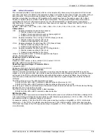
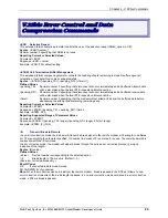
V.22bis Error Control and Data
Compression Commands

+ESR

Selective Repeat

This extended-format numeric parameter controls the use of the selective repeat (SREJ) option in V.42

.

Syntax

+ESR=[<value>]

Decimal number 0 specifying that SREJ is not used.

Reporting Current or Selected Values:

Command: +ESR?
Response: +ESR: <value>
Example: +ESR: 0 For default setting

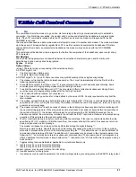
+ETBM Call Termination Buffer Management

This extended-format compound parameter controls the handling of data remaining in modem buffers upon call
termination. It accepts three numeric subparameters:

Syntax   

+ETBM=[<pending_TD>[,<pending_RD>[,<timer>]]]

Defined Values

<pending_TD>  Decimal number 0 specifying that disconnect will occur immediately and all buffered transmit data

will be discarded when the local DTE requests call disconnection.

<pending_RD>  Decimal number 0 specifying that disconnect will occur immediately and all buffered receive data

will be discarded when the local DTE requests call disconnection.

<timer> 

Decimal number 0 specifying that the modem will not attempt to deliver the buffered data before
abandoning the attempt and discarding remaining data.

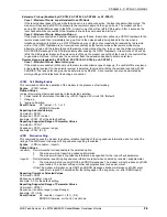
Reporting Current or Selected Values

Command: +ETBM?
Response: +ETBM: <pending_TD>,<pending_RD>,<timer>
Example: +ETBM: 0,0,0

Reporting Supported Range of Parameter Values

Command: +ETBM=?
Response: +ETBM: (<pending_TD> range),(<pending_RD> range),(<timer> range)
Example: +ETBM: (0),(0),(0)

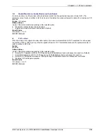
\B

Transmit Break to Remote

In non-error correction mode, the modem will transmit a break signal to the remote modem with a length in multiples
of 100 ms according to parameter specified. If a number in excess of 9 is entered, 9 is used. The command works in
conjunction with the \K command

.

In error correction mode, the modem will signal a break through the active error correction protocol, giving no
indication of the length.

Syntax

\B<value>

Defined Values

<value> 

Decimal number corresponding to the selected option.

1-9 

Break length in 100 ms units. (Default = 3.)

(Non-error corrected mode only.)

Result Codes

OK 

If connected in data modem mode

NO CARRIER If not connected.

Note: 

When the modem receives a break from the remote modem, break is passed to the DTE as follows: In non-

error correction mode direct, the break length is passed; in non-error correction mode normal and in error correction
mode, a 300 ms break is passed.

Summary of Contents for SocketModem MT2456SMI-22

Page 1: ...SocketModemÔ Embedded Modem MT2456SMI 22 Serial Interface Developer s Guide ...

Page 2: ... SocketModem and the Multi Tech logo Microsoft Windows Windows 95 Windows NT and Windows 2000 are registered trademarks or trademarks of Microsoft Corporation in the United States and or other countries Patents This device covered by one or more of the following patents 6 031 867 6 012 113 6 009 082 5 905 794 5 864 560 5 815 567 5 815 503 5 812 534 5 809 068 5 790 532 5 764 628 5 764 627 5 754 589...

Page 3: ...ommands 12 V 22bis DTE DCE Modem Interface commands 15 V 22bis Call Control Commands 21 V 22bis Modulation Control Commands 27 V 22bis Error Control and Data Compression Commands 29 V 22bis Synchronous Access Mode Commands 31 V 22bis FastConnect Command 33 V 22bis Line Side Device Commands 34 V 22bis S Parameters 35 V 22bis Result Codes 45 Appendix A Test Demo Card Information 47 Block Diagram 47 ...

Page 4: ...equirements globally and can be shipped worldwide This guide provides the information needed to effectively integrate the SocketModem into your equipment It also includes the AT commands for the configuration and control of a data modem and the result codes that the modem issues in response to the commands Product Description The MT2456SMI SocketModem is a standard 64 pin modem used for integratin...

Page 5: ...s Transmit Level 12 dBm varies by country setting Frequency Stability 0 01 Receiver Sensitivity 43 dBm under worst case conditions Interface Serial ITU T V 24 logical interface Diagnostics Local analog loop Weight 0 02 Kg 0 04 lb Dimensions 1 045 2 541 0 680 2 7 x 6 5 x 1 8 cm Power Consumption Typical 70 mA 235 W 3 3V DC Maximum 80 mA 264 W 3 6V DC Operating Voltage Typical 3 3V DC 5 Absolute Max...

Page 6: ...Chapter 2 Mechanical Specifications Multi Tech Systems Inc MT2456SMI 22 SocketModem Developer s Guide 6 Chapter 2 Mechanical Specifications Physical Dimensions Figure 2 1 Maximum Component Height ...

Page 7: ...e AT command set to the original factory default values or to stored values in NVRAM RESET is tied to VCC through a 250 ms time constant circuit for Power on Reset functionality The modem is ready to accept commands within 6 5 seconds of power on or reset Reset must be asserted for a minimum of 300 ns 26 DGND Ground 29 DCDIND DCD LED Indicator 30 RXIND RXD LED Indicator 31 DTRIND DTR LED Indicator...

Page 8: ...oss the interface on TXD 39 DCD O Data Carrier Detect DCD output is ON low when a carrier is detected on the telephone line or OFF high when carrier is not detected 40 DTR I Data Terminal Ready Active Low The DTR input is turned ON low by the DTE when the DTE is ready to transmit or receive data DTR ON prepares the modem to be connected to the telephone line and once connected maintains the connec...

Page 9: ...D 35 RTS 33 RESET 24 Min 2 0 V Max 0 8 V Outputs Output High Output Low DCD 39 CTS 38 DSR 37 RI 36 RXD 34 2mA Z INT 120 Ω Digital Input Capacitance Min 2 4 V Max 0 4 V 50pF Handling Precautions All electronic devices should be handled with certain precautions to avoid damage due to the accumulation of static charge Although input protection circuitry has been incorporated into the devices to minim...

Page 10: ...rol X Extended Result Codes Call Progress Information C RLSD Option D DTR Option K Flow Control R RTS CTS Option G Modem to Modem Flow Control XON XOFF IFC DTE Modem Local Flow Control IBC In Band Commands Call Control Commands D Dial T Set Tone Dial Default P Set Pulse Dial A Answer H Disconnect Hang Up O Return to On line Data Mode L Monitor Speaker Volume M Monitor Speaker Mode Control G Select...

Page 11: ...olds Fast Connect Command F Fast Connect Control Line Side Device Commands TTE Threshold Adjustments for Telephony Extension TRV Tip and Ring Voltage Measurement A Note About Compatibility Commands You may notice that some commands are available but do not support any function These commands exist for compatibility purposes only If you enter these commands you may receive an OK result however no c...

Page 12: ...h unformatted presentation to the DTE Reporting Current or Selected Values Command VCID Response VCID pmode Example VCID 0 For the default setting Reporting Supported Range of Parameter Values Command VCID Response VCID pmode range Example VCID 0 2 VRID Report Retrieved Caller ID CID This command reports the data associated with the Caller ID services in the Incoming Call Line ID ICLID data format...

Page 13: ...identification codes RevisionName masked firmware code version Example Patton Modulation V 22bis Example Patton V22B 4 Reports OEM defined identifier string in either Hayes compatible binary format default e g a007040284C6002F bC60000000r10051111510120003000111170000000 5 Reports Country Code parameter see GCI 6 Reports OK 7 Reports OK Result Codes OK value 0 7 ERROR Otherwise GCI Country of Insta...

Page 14: ...al number corresponding to the selected option 0 Terminates test in progress Clears S16 1 Initiates local analog loopback V 54 Loop 3 Sets S16 bit 0 If a connection exists when this command is issued the modem hangs up The CONNECT XXXX message is displayed upon the start of the test Load to Internal RAM This command allows the internal SRAM to be loaded with patch code for minor firmware upgrade i...

Page 15: ...orm result codes to the DTE The parameter if valid is written to S14 bit 3 Syntax V value Defined Values value Decimal number corresponding to the selected option 0 Enables short form terse result codes Line feed is not issued before a short form result code 1 Enables long form verbose result codes Default Result Codes OK value 0 or 1 ERROR Otherwise W Connect Message Control This command in conju...

Page 16: ...The value 100b is written to S22 bits 6 5 and 4 respectively 2 Disables reporting of busy tones unless forced otherwise by country requirements send only OK CONNECT RING NO CARRIER ERROR NO DIAL TONE NO ANSWER and CONNECT XXXX If busy tone detection is enforced and busy tone is detected NO CARRIER will be reported instead of BUSY If dial tone detection is enforced or selected and dial tone is not ...

Page 17: ...4 Also see S25 Syntax D value Defined Values value Decimal number corresponding to the selected option 0 DTR drop is interpreted according to the current Qn setting as follows Q0 Q5 Q6 DTR is ignored assumed ON Allows operation with DTEs which do not provide DTR Q1 DTR drop causes the modem to hang up Auto answer is not affected Q2 Q3 DTR drop causes the modem to hang up Auto answer is inhibited 1...

Page 18: ...dem to modem XON XOFF flow control Default 1 Enables modem to modem XON XOFF flow control Result Codes OK value 0 or 1 ERROR Otherwise IFC DTE Modem Local Flow Control This extended format compound parameter controls the operation of local flow control between the DTE and the modem during the data state when V 42 error control is used or when fallback to non error control mode is specified to incl...

Page 19: ...rted circuit types hook Not supported leave 0 Reporting Current or Selected Values Command IBC Response IBC value value value 0 0 0 0 value 0 0 0 0 0 Example IBC 0 0 0 0 0 0 0 0 0 0 0 0 0 Reporting Supported Range of Parameter Values Command IBC Response IBC 0 2 0 1 0 1 0 0 0 0 0 1 0 0 0 0 0 Entering and Exiting In Band Active State In Band Command mode will be active only when a modem connection ...

Page 20: ...esponds to EM shielded AT commands via the extend 0 CONTROL sequence This command may be used to transmit any AT commands to the modem as follows EM extend 0 length CONTROL AT Command without AT and trailing carriage return Upon receipt of an in band command the modem responds with the extend 0 STATUS REPORT sequence This sequence will contain the response to the AT command issued via the CONTROL ...

Page 21: ...d on Flash the modem will go on hook for a time defined by the value of S29 Country requirements may limit the time imposed W The modem will wait for dial tone before dialing the digits following W If dial tone is not detected within the time specified by S7 U S or S6 other countries the modem will abort the rest of the sequence return on hook and generate an error message The modem will wait for ...

Page 22: ...mmand initiates a hang up sequence It may not be available for some countries due to PTT restrictions Syntax H value Defined Values value Decimal number corresponding to the selected option 0 The modem will release the line if the modem is currently on line and will terminate any test AT T that is in progress Country specific modulation specific and error correction protocol specific S38 processin...

Page 23: ...mand may not be permitted in some countries Result Codes OK value 0 to 2 ERROR Otherwise P Select Pulse Dial Make Break Ratio This command determines the make break ratio used during pulse dialing It is only effective if the appropriate bit to enable this command is set through the country profile The default is country dependent The parameter value if valid is written to S28 bits 3 and 4 Syntax P...

Page 24: ...n Note Modulation is omitted for all other modulations Protocol NONE for no protocol ALT for Microcom Network Protocol LAPM for LAP M protocol Line Speed Asymmetric rates are displayed as rate TX rate RX e g 1200 TX 75 RX Symmetric rates are displayed as a single DCE rate e g 2400 L Report Line Signal Level Returns a value which indicates the received signal level The value returned is a direct in...

Page 25: ...d and Line in Use disabled Reporting Supported Range of Parameter Values Command STE Show available options Response STE 0 7 Result Codes OK value 0 7 ERROR Otherwise Behavior in Data Mode When on hook if the line is in use and an ATDT is issued the modem will not go off hook and will return with the message LINE IN USE When off hook and either an extension is picked up or a line reversal is detec...

Page 26: ...ected the modem will drop the call and respond with NO CARRIER The reason for hang up can be determined by S86 25 A line reversal can also be simulated by simply pulling out the telephone line during a connection PCW Call Waiting Enable This command controls the operation of the modem in the presence of call waiting Syntax PCW value Defined Values value Decimal number corresponding to the selected...

Page 27: ...n May be used to condition distinct limits for the receive direction as distinct from the transmit direction Values for this subparameter are decimal encoded in units of bit s Actual values will be limited to possible values corresponding to the entered carrier and fall back carrier as determined during operation Default lowest min_rx_rate and highest max_rx_rate rate supported by the selected car...

Page 28: ...es OK value 0 or 2 ERROR Otherwise B ITU T or Bell When the modem is configured to allow either option the modem will select Bell or ITUT modulation for a line speed connection of 300 or 1200 bps Any other line speed will use an ITU T modulation standard The parameter value if valid is written to S27 bit 6 Syntax B value Defined Values value Decimal number corresponding to the selected option 0 Se...

Page 29: ...hat the modem will not attempt to deliver the buffered data before abandoning the attempt and discarding remaining data Reporting Current or Selected Values Command ETBM Response ETBM pending_TD pending_RD timer Example ETBM 0 0 0 Reporting Supported Range of Parameter Values Command ETBM Response ETBM pending_TD range pending_RD range timer range Example ETBM 0 0 0 B Transmit Break to Remote In n...

Page 30: ...ata Default The second case is where the modem is in the on line command state waiting for AT commands during a data connection and the B is received in order to send a break to the remote modem 0 Clear data buffers and send break to remote modem 1 Clear data buffers and send break to remote modem Same as 0 2 Send break to remote modem immediately 3 Send break to remote modem immediately Same as 2...

Page 31: ...fault and fixed framed_un_ov Specifies the actions undertaken by the modem when a transmit data buffer under run or overrun condition occurs immediately after a non flag octet while operating in Framed sub Mode 0 In Framed sub Mode modem transmits abort on under run in middle of frame default 1 In Framed sub Mode DCE transmits a flag on under run in middle of frame and notifies DTE of under run or...

Page 32: ...ing EM codes received from the DTE with the exception of DC1 and DC3 if these are used to signal modem by DTE flow control The modem returns the ERROR result code if the DTE specifies that the off subparameter be set to a value less than or equal to the on subparameter in this case the current parameter value settings are not modified on Determines the threshold in octets below which the modem wil...

Page 33: ...he client modem to connect to a central site modem that supports non standard V 22 and V 22bis Fast Connect protocols Syntax F n Defined Values n Decimal number which specifies the initial requested mode of operation when the modem is operating as the originator The options are 0 Normal connection Default 1 Fast Connect without answer tone 2 Reserved 3 Fast Connect with answer tone ...

Page 34: ...his value must be greater than the Extension Pickup voltage drop threshold AT TTE Queries current setting Notes 1 All thresholds are difference thresholds Example The line would be considered in use if the Tip Ring Voltage dropped by 10 00 volts Another Example If the modem is off hook and the voltage drops by more than 2 50 volts then the modem would consider the condition as an extension pick up...

Page 35: ... n to the value v n Reports the value of S Parameter n The parameter n can be omitted in which case the last S Parameter accessed will be assumed The S can be omitted for AT and AT in which case the last S Parameter accessed will be assumed For example ATS7 establishes S7 as the last accessed register AT 40 sets the contents of the last register accessed to 40 ATS 20 sets the contents of the last ...

Page 36: ...ions Status 138 8Ah S16 Test Mode Bit Mapped Options Status 0 S19 Reserved 0 S20 Reserved 0 S21 V 24 General Bit Mapped Options Status 52 34h S22 Speaker Results Bit Mapped Options Status 117 75h S23 General Bit Mapped Options Status 0 S24 Sleep Inactivity Timer 0 255 s 0 S25 Delay to DTR Off 0 255 s or 0 01 s 5 S26 RTS to CTS Delay 0 255 0 01 s 1 S27 General Bit Mapped Options Status 73 49h S28 G...

Page 37: ...ed the modem echoes back to the local DTE the Backspace character an ASCII space character and a second Backspace character this means a total of three characters are transmitted each time the modem processes the Backspace character Range 0 32 ASCII decimal Default 8 Backspace S6 Wait Time before Blind Dialing or for Dial Tone S6 operation is country dependent 1 Sets the length of time in seconds ...

Page 38: ...ier Range 1 255 tenths of a second Default 14 1 4 seconds S11 DTMF Tone Duration S11 operation is country dependent 1 For U S S11 sets the duration of tones in DTMF dialing has no effect on pulse dialing 2 For other countries S11 is a country parameter loaded via patch code Range 50 255 milliseconds Default 95 95 milliseconds S12 Escape Prompt Delay EPD S12 defines the maximum period in fiftieths ...

Page 39: ... Not used S19 Reserved S19 is supported for backwards compatibility only No value can be written Responds with default value Range None Default 0 S20 Reserved S20 is supported for backwards compatibility only No value can be written Responds with default value Range None Default 0 S21 V 24 General Bit Mapped Options Status S21 indicates the status of command options Default 52 34h 00110100b Bits 0...

Page 40: ...ength of time in seconds that the modem will operate in normal mode with no detected telephone line or DTE line activity before entering low power sleep mode The timer is reset upon any DTE line or telephone line activity If S24 is zero neither DTE line nor telephone inactivity will cause the modem to enter the sleep mode Range 0 255 seconds Default 0 S25 Delay To DTR Off S25 sets the length of ti...

Page 41: ... length of time in units of 10 ms that the modem will go on hook when it encounters the flash dial modifier in the dial string S29 is a country dependent parameter The S29 value cannot be changed using S29 XX Range 0 255 10 ms intervals Default 70 700 ms for U S S30 Disconnect Inactivity Timer S30 sets the length of time in tens of seconds that the modem will stay online before disconnecting when ...

Page 42: ...at V 22 1200 bps F4 6 Attempt to connect at V 22bis 2400 bps F5 7 Attempt to connect at V 23 F3 Bits 4 7 Reserved S38 Delay Before Forced Hang Up S38 specifies the delay between the modem s receipt of the H command to disconnect or ON to OFF transition of DTR if the modem is programmed to follow the signal and the disconnect operation Applicable to error correction connection only This parameter c...

Page 43: ...een entered Range 3 7 or 128 Default 128 S82 3 Expedited Modem sends a break immediately data integrity is maintained ahead of and after the break S82 7 Destructive Modem sends a break immediately data being processed by each modem at the time of the break is destroyed S82 128 In sequence Modem sends a break in sequence with any transmitted data data integrity is maintained both ahead of and after...

Page 44: ...ing to 0 to 15 dBm transmit level Default 10 10 dBm transmit level S95 Extended Result Codes Control A bit set to a 1 in this parameter in conjunction with the W command will enable the corresponding extended result code The W command determines the corresponding actual result code reporting see W command Default 0 Bit 0 CONNECT result code indicates DCE speed instead of DTE speed Bit 1 Append ARQ...

Page 45: ...cted 4 ERROR Sent during an attempt to execute a command line if any of the following conditions occur 1 The command line contains a syntax error 2 The modem cannot execute a command contained in the command line i e the command does not exist or is not supported 3 A command parameter within the command line is outside the permitted range For X0 X1 X2 and X3 this message is sent instead of DELAYED...

Page 46: ...600 bps and DTE speed reporting is enabled 62 CONNECT 24000 The modem has connected to the line the DTE speed is 24000 bps and DTE speed reporting is enabled 63 CONNECT 26400 The modem has connected to the line the DTE speed is 26400 bps and DTE speed reporting is enabled 64 CONNECT 28800 The modem has connected to the line the DTE speed is 28800 bps and DTE speed reporting is enabled 83 LINE IN U...

Page 47: ...SocketModem Developer s Guide 47 Appendix A Test Demo Card Information Block Diagram Speaker DS1 Modem Module Power Supply Power Switch Power Connector RJ 11 Connector DB 25 RS 232 Volume Control Tip Ring Fuse Transceiver RS 232 Figure A 1 Serial Test Demo Board Block Diagram ...

Page 48: ...for operation in all countries The following list is displays the country approvals as of April 1 2003 This information can be deemed reliable but is not guaranteed All information is subject to change Contact your Multi Tech Systems Inc sales representative or call the world headquarters at 800 328 9717 Country Country Code US B5 Canada B5 Austria B5 Belgium B5 Cyprus B5 Denmark B5 Finland B5 Fra...

Page 49: ...low Other vendor products may or may not operate satisfactorily Multi Tech System s recommended vendor products only indicate that the product has been tested in controlled conditions and were found to perform satisfactorily Figure B 1 Recommended Main Board Filtering Surface mount ferrites are used on T R Tip and Ring to mitigate emission levels out the RJ 11 cable 220pF capacitors are also used ...

Page 50: ...ctor Manufacturer Teccor Electronics Part P 3100SA Manufacturer ST Microelectronics Part 1 SMP100 270 Recommended Transceiver Manufacturer Analog Devices Part ADM207EAR Safety All creepages and clearances for the MT2456SMI have been designed to meet requirements of safety standards EN 60950 The requirements are based on a working voltage of 250V When the recommended DAA circuit interface is implem...

Page 51: ... possbile to the line jack F 0 035 0 889 Drill with 0 060 1 524 Pad 0 125 3 175 Non Plated 1 732 44 750 19 05 0787 TYP 2 945 24 003 145 3 683 Figure B 3 SocketModem Placement Note The dimensions in this diagram are examples only See the mechanical drawing in Chapter 2 for true dimensions Key Qty Ref Name Description 1 A Reference Generic Motherboard 1 B or C Recommended RICHCO DLMSPM 4 01 Support ...

Page 52: ...e number REN for this equipment or a product identifier in the format US AAAEQ TXXXX If requested this number must be provided to the telephone company 2 A plug and jack used to connect this equipment to the premises wiring and telephone network must comply with the applicable FCC Part 68 rules and requirements adopted by the ACTA It s designed to be connected to a compatible modular jack that is ...

Page 53: ... TXXX Where US Is a fixed field that indicates the equipment meets all requirements of 47 CFR Part 68 including the requirements published by ACTA AAA is the responsible party s Grantee Code obtained previously from the FCC s Common Carrier Bureau or currently from ACTA EQ Is an Equipment Code indicating to the Service Provider any special signal handling or billing requirements The Equipment code...

Page 54: ...ted to a telephone interface The termination on an interface may consist of any combination of devices subject only to the requirement that the sum of the RENs of all the devices does not exceed five Pursuant to section 69 3 of the Telecommunications Act Certified or self declared TE will bear a valid identifying certification or registration number The marking of the certification or registration...

Page 55: ...ement form completed by the proposed multiple listee e A drawing sample or illustration of the product label and f Payment in accordance with TRC 49 section on Multiple Listings New Zealand Telecom Warning Notice 1 The grant of a Telepermit for any item of terminal equipment indicates only that Telecom has accepted that the item complies with minimum conditions for connection to its network It ind...

Page 56: ...n total of the RN s of all devices connected to a single line at any time should not exceed 5 International Modem Restrictions Some dialing and answering defaults and restrictions may vary for international modems Changing settings may cause a modem to become non compliant with national telecom requirements in specific countries Also note that some software packages may have features or lack restr...

Page 57: ... 7 Placement SocketModem 51 Product Approvals 48 Safety considerations 50 Serial Demo Board block diagram 47 South African Statement Regulations 56 Specifications Mechanical 6 Specifications Technical 5 STE Set Telephony Extension 25 T Set Tone Dial Default 22 Table of Result Codes 16 Technical Specifications 5 TRV Tip and Ring Voltage Measurement 34 TTE Threshold Adjustments for Telephony Extensi...

Page 58: ...ker Results Bit Mapped Options Status 40 S23 General Bit Mapped Options Status 40 S24 Sleep Inactivity Timer 40 S25 Delay To DTR Off 40 S26 RTS to CTS Delay 40 S27 Bit Mapped Options Status 41 S28 Bit Mapped Options Status 41 S29 Flash Dial Modifier Time 41 S3 Carriage Return Character 37 S30 Disconnect Inactivity Timer 41 S31 Bit Mapped Options Status 41 S36 LAPM Failure Control 42 S37 Desired Li...

Reviews: