


BOARD COMPONENTS
28
MultiConnect
®
PCIe MTPCIE-EV3 Developer Guide
Chapter 8 – Board Components
Note that MTPCIE-EV3 models do not include Bluetooth/WiFi.
Jumper
Description
JP3, JP4, JP5, JP48
Selects CGND or GND for antenna holder grounding. Default is CGND.
JP6
JP6 allows you to select either the internal 5V regulator (INT PWR) or to choose EXT
5V (EXT PWR). For the EXT PWR, you can use your own external 5V power source
and plug it into J11.
JP43, JP44
Not used by PCIe devices.
JP45
Board Power. Default is installed.
JP49
Probes for connecting speaker.
JP50
Probes for connecting microphone.
JP51, JP52
Debugging probes for PCIE connector J23.
JP53, JP54
Selects USB host connected to PCIe device. Pins 1 & 2 jumpered select external USB
host connected to J4.
JP57, JP58
Selects USB host connected to quad serial UART U20. Pins 1 & 2 jumpered select
external USB host connected to J24.
JP59, JP60, JP61,JP63,JP64,
JP69
Selects serial connection for PCIe device. Pins 1 & 2 jumpered select DB9 connector
J1 connected to PCIe device. Pins 2 & 3 jumpered select quad UART U20 connected
to PCIe device. All jumpers must be moved to the same position.
JP65, JP66, JP67, JP68
Selects serial connection for PCIe Bluetooth device. Pins 1 & 2 jumpered select DB9
connector J14 connected to PCIe Bluetooth device. Pins 2 & 3 jumpered select quad
UART U20 connected to PCIe Bluetooth device. All jumpers must be moved to the
same position.
JP70
Probes for PCIe GPIO2 & GPIO3. The pin next to the text "GPIO_3.3V" is GPIO3. The
center pin is GPIO2.
JP73, JP74
Not used by PCIe devices.
JP75, JP76, JP77, JP78
When these jumpers are installed, DVI interface of audio codec U84 is connected to
DVI interface of PCIe device. By removing these jumpers when connecting an
external DVI device.
JP79, JP80
Use these jumper pins to connect an external DVI device.
JP81, J82
Selects source for programming audio codec U84. Pins 1 & 2 jumpered select MICRO
U84 as source. Default is MICRO.
JP83, JP84
These pins can be used for programming MICRO U84.
JP85
Selects power source for MICRO U85. Default is 1.8v
JP86
May be used to manually reset PCIe Bluetooth device by briefly installing and then
removing a jumper. Default is no jumper installed.
JP87
Not applicable for this device.
Summary of Contents for MultiConnect MTPCIE-EV3
Page 1: ...MultiConnect PCIe MTPCIE EV3 Developer Guide ...
Page 15: ...DEVELOPER BOARD MultiConnect PCIe MTPCIE EV3 Developer Guide 15 ...
Page 17: ...ASSEMBLY DIAGRAM MultiConnect PCIe MTPCIE EV3 Developer Guide 17 Bottom ...
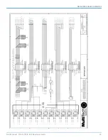
Page 20: ...DEVELOPER BOARD SCHEMATICS 20 MultiConnect PCIe MTPCIE EV3 Developer Guide ...
Page 21: ...DEVELOPER BOARD SCHEMATICS MultiConnect PCIe MTPCIE EV3 Developer Guide 21 ...
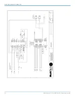
Page 22: ...DEVELOPER BOARD SCHEMATICS 22 MultiConnect PCIe MTPCIE EV3 Developer Guide ...
Page 23: ...DEVELOPER BOARD SCHEMATICS MultiConnect PCIe MTPCIE EV3 Developer Guide 23 ...
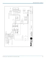
Page 24: ...DEVELOPER BOARD SCHEMATICS 24 MultiConnect PCIe MTPCIE EV3 Developer Guide ...
Page 25: ...DEVELOPER BOARD SCHEMATICS MultiConnect PCIe MTPCIE EV3 Developer Guide 25 ...
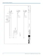
Page 26: ...DEVELOPER BOARD SCHEMATICS 26 MultiConnect PCIe MTPCIE EV3 Developer Guide ...
Page 27: ...DEVELOPER BOARD SCHEMATICS MultiConnect PCIe MTPCIE EV3 Developer Guide 27 ...


