


26
CommPlete 4000 Communications Server Overview
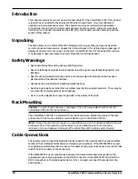
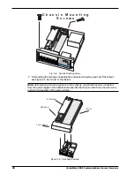
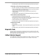
C h a s s i s M o u n t i n g
S c r e w s
BANK 1
BANK 1
M1
M2
M3
M4
SOCKET 7
LOCK
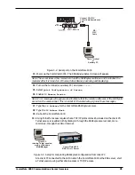
Fig. 4-4. Chassis Mounting Screw
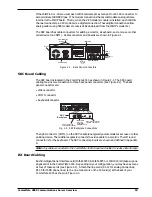
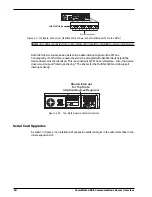
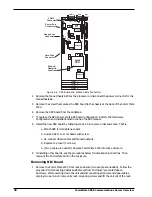
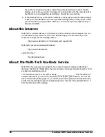
4 Finish pulling the card cage (including fan enclosure) straight up and out of the chassis.
See Figure 4-5. Set it next to the chassis.
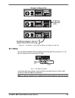
Note
: Before placing the card cage back into the chassis, verify that the power connectors
from the power supply to the backplane are fully attached. Figure 4-5b shows the wire colors
and correct orientation of the power cables.
ISI (3)
SBC Board
BANK 1
SOCKET 7
LOCK
M4
M3
BANK 1
M2
M1
Ethercard
BANK 1
BANK 1
M1
M2
M3
M4
SOCKET 7
LOCK
Fan Enclosure
Figure 4-5. Card Cage Removal
Summary of Contents for CommPlete 4000
Page 1: ...CommPlete 4000 Communications Server User Guide...
Page 5: ...CommPlete 4000 Communications Server Overview 5 1 System Overview...
Page 10: ...10 CommPlete 4000 Communications Server Overview...
Page 11: ...CommPlete 4000 Communications Server Overview 11 2 Installing Your CommPlete 4000...
Page 16: ...16 CommPlete 4000 Communications Server Overview...
Page 17: ...CommPlete 4000 Communications Server Overview 17 3 Getting Started with RASExpress...
Page 23: ...CommPlete 4000 Communications Server Overview 23 4 Hardware removal Replacement...
Page 33: ...CommPlete 4000 Communications Server Overview 33 5 Troubleshooting...
Page 36: ...36 CommPlete 4000 Communications Server Overview...
Page 37: ...CommPlete 4000 Communications Server Overview 37 6 Service Warranty and Technical Support...
Page 41: ...CommPlete 4000 Communications Server Overview 41 Appendices...