background image

PAGE 28 — TP24X TILE SAW • OPERATION AND PARTS MANUAL — REV. #4 (09/12/19) 

REALIGNMENT

Method 1

This procedure deals with the most common source of 

misalignment that occurs when the guide rails are not 

parallel with the blade.
1.  Set the cutting depth such that the blade passes 

through the table, not over.

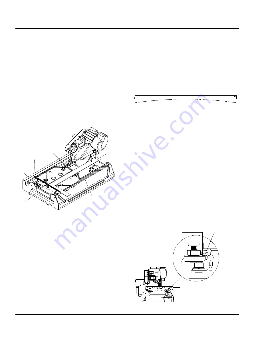
2.  Place a straight edge (i.e. carpenter’s square) on the 

cutting table as shown in Figure 22.

3.  Loosen the left and right guide rails by loosening the 

fasteners found at the ends of the rail. The left rail 

should be slightly loose, so there is not too much play 

during adjustments, but the right rail should move freely.

Figure 22. Realigning Guide Rails

4.  Make sure the short portion of the straight edge is placed 

flush against the ruler guide.  Adjust the left guide rail 

so that the front and rear edges of the blade touch the 

straight edge, although a tolerance of 0.1mm (.004 in.) 

between the front and rear edges is allowed.  Perform this 

adjustment along the entire length of the straight edge.

5.  Position the table as close to the user as possible.  Place 

the straight edge flush against the ruler guide and blade.  

Without holding onto the straight edge, gently move 

the table towards the rear of the saw and then back.  

Observe any gaps that may appear between the straight 

edge and blade or between the straight edge and ruler 

guide.  A gap exceeding the allowed tolerance means 

that the table is not moving parallel to the blade; hence, 

FASTENER

RULER

GUIDE

STRAIGHT

EDGE

RIGHT
GUIDE

RAIL

LEFT

GUIDE

RAIL

FRONT

OF THE

SAW

further adjustments as outlined below will be required.  

However, if scenario A or B (described below) occurs, 

other adjustments may be required instead.
a.  If the straight edge only touches the blade when 

the table is positioned midway along the rail or at 

the ends of the rail, then the rail may be deformed 

(i.e. bowed). See Figure 23. Perform test cuts to 

determine if the rail should be replaced.  Typically, 

a bowing displacement of up to 0.2mm (.008 in.) 

will not affect cutting accuracy.

Figure 23. Rail Deformation

b.  If the straight edge touches both edges of the blade 

intially, but shifts apart as the table travels  along 

the rail, proceed to Method 2.

6.  Tighten the fasteners at both ends of the left rail.
7.  Adjust the right guide rail so that the horizontal rollers 

underneath the table engage the rail as shown in 

Figure 24.  In most cases the rollers will not have to 

be vertically adjusted.  Spacing between rails must 

be equidistant at all points to ensure that they are 

parallel.  Once adjustments are made, lightly tighten 

the fasteners on the right rail and move the table back 

and forth.  If the table binds against the rail at any 

point, adjust spacing accordingly until the table moves 

smoothly.

8.  Tighten the fasteners at both ends of the right rail.
If alignment has been achieved, do not proceed to Method 2.

Figure 24. Adjust Right Guide Rail

LEAVE HAIRLINE GAP
BETWEEN RAIL AND ROLLER

LEAVE A 1/32 IN.

(1MM) GAP 

MAINTENANCE

Summary of Contents for TP24X

Page 1: ...D PARTS MANUAL THIS MANUAL MUST ACCOMPANY THE EQUIPMENT AT ALL TIMES MODEL TP24X TILE SAW ELECTRIC MOTOR Revision 4 09 12 19 To find the latest revision of this publication visit our website at www mu...

Page 2: ...PAGE 2 TP24XTILE SAW OPERATION AND PARTS MANUAL REV 4 09 12 19 PROPOSITION 65 WARNING...

Page 3: ...cancer birth defects or other reproductive harm If you are unfamiliar with the risks associated with the particular process and or material being cut or the composition of the tool being used review...

Page 4: ...c Motor Components 16 Set Up 16 20 Sawing Guides 20 21 Operation 22 23 Maintenance 24 30 Wiring Diagram Electric Motor 31 Troubleshooting Blade 32 Troubleshooting Saw 33 Explanation Of Code In Remarks...

Page 5: ...TP24XTILE SAW OPERATION AND PARTS MANUAL REV 4 09 12 19 PAGE 5 NOTES...

Page 6: ...sure to the operator and are preceded by one of four words DANGER WARNING CAUTION or NOTICE SAFETY SYMBOLS DANGER Indicates a hazardous situation which if not avoided WILL result in DEATH or SERIOUS I...

Page 7: ...while the equipment is in operation No one other than the operator is to be in the working area when the equipment is in operation ALWAYS check the equipment for loosened threads or bolts before start...

Page 8: ...ldren and unauthorized personnel BLADE SAFETY WARNING Rotating blade can cut and crush ALWAYS keep hands and feet clear while operating the saw CAUTION NEVER operate the saw without blade guards and c...

Page 9: ...cords will not be tripped over or trapped underneath the saw Never use the cable to pull out the plug from the power source NOTICE ALWAYS make certain that proper power or extension cord has been sel...

Page 10: ...led Cutting Head Cast Aluminum Adjustable Conveyor Cart Aluminum with roller bearings injected molded rubber pad transportation lock Drive System V belt Max Depth of Cut 3 1 2 in 90 mm Straight Cut 24...

Page 11: ...TP24XTILE SAW OPERATION AND PARTS MANUAL REV 4 09 12 19 PAGE 11 DIMENSIONS Table 3 Dimension Reference Letter Dimensions A 38 2 in 970mm B 22 6 in 574 mm C 20 6 in 523 mm A B C Figure 1 Dimensions...

Page 12: ...of this saw is best evidenced by using 10 inch 250 mm diamond blades that match the material being cut Ask your dealer or call Multiquip regarding the proper diamond tool selection for your applicati...

Page 13: ...TP24XTILE SAW OPERATION AND PARTS MANUAL REV 4 09 12 19 PAGE 13 NOTES...

Page 14: ...PAGE 14 TP24XTILE SAW OPERATION AND PARTS MANUAL REV 4 09 12 19 SAW COMPONENTS 1 3 12 13 14 15 17 18 19 21 23 22 20 4 2 5 8 9 10 11 6 24 16 7 Figure 2 Saw Components...

Page 15: ...vents foreign matter and debris from accumulating on the saw blade Replace brushes immediately when they become worn or damaged 13 CuttingTable Place material to be cut on this rubber padded table For...

Page 16: ...the power ON OFF switch in the OFF position and disconnect the plug from the power source 3 If using the optional support stand assemble as described in the Support Stand Assembly section Make sure t...

Page 17: ...de or interfere with any moving parts Figure 5 Water Pump and Water Tray 7 Insertthewaterpumppowerplugintotheoutletreceptacle on the electric motor conduit box as shown in Figure 6 Figure 6 Water Pump...

Page 18: ...or Rim Ensure that there are no cracks dings or missing portions of the diamond segment rim DO NOT use a blade that is missing a segment or a portion of the rim Damaged and or missing segments rims m...

Page 19: ...cutting head so that the blade is 1 4 6 mm below the surface of the cutting table Tighten the adjustment knob firmly to hold the cutting head in place Figure 9 Blade Installation See Table 5 for prop...

Page 20: ...E OPTION CONNECTINGTHE POWER 1 Place the power ON OFF switch Figure 10 in the OFF position down 2 Connectanextensioncordofadequatecurrentcarrying capacity to the power plug on the electric motor 3 MAK...

Page 21: ...uler guide Tighten threaded knob once in place 2 Place one corner of the material being cut into the template and rest the adjacent corner against the ruler guide Whencuttingthetileintwoequalhalves th...

Page 22: ...RNING NEVER place hands and fingers near the cutting blade The possibility exists of severe bodily harm if hands and fingers come in contact with rotating saw blade WARNING ALWAYS ensure that the cutt...

Page 23: ...otected with a manual reset thermal overload switch that will turn the saw off if the motor is overheated In the event that the switch is tripped turn the ON OFF switch to the OFF position and allow t...

Page 24: ...g Place power ON OFF switch to the OFF position Disconnect power cord from AC source NEVER attempt to check the V belt with the engine running Severe bodily injury can occur 5 After each day s use run...

Page 25: ...on the guide rails and that it easily moves along the entire length of the rails With the saw blade removed switch on the motor for an instant and switch it off again If the motor does not run have t...

Page 26: ...guard 3 Loosen the 4 bolts located at the base of the motor 4 Use a hex wrench to access the socket hex bolt located at the rear of the cutting head Turn wrench to move the motor forward thus providi...

Page 27: ...To install a new bearing housing perform the following 1 Make sure that the old housing has been properly removed 2 Unpack the new bearing housing and place the flat portion face down on a towel situa...

Page 28: ...he table is not moving parallel to the blade hence FASTENER RULER GUIDE STRAIGHT EDGE RIGHT GUIDE RAIL LEFT GUIDE RAIL FRONT OF THE SAW further adjustments as outlined below will be required However i...

Page 29: ...ORIZONTAL ROLLER CLEARANCE RIGHT GUIDE RAIL LOOSEN FASTENERS FLAT SCREW DRIVER 13MM SOCKET WRENCH RUBBER CAP C RUBBER CAP B RUBBER CAP A MAINTENANCE Figure 27 Remove Table 3 If the table shifts to the...

Page 30: ...to maintain contact with the guide rails If the table is not perpendicular to the blade lift the right side of the table instead to obtain the proper angle A square tool will be required to confirm t...

Page 31: ...4 09 12 19 PAGE 31 WIRING DIAGRAM ELECTRIC MOTOR Power Outlet for Water Pump Green Motor Overcurrent Breaker Wiring Box Green Green White White White Black Black Black Black White Black Switch Power C...

Page 32: ...is blunt Saw blade type is unsuitable for the material being cut Use appropriate type of saw blade Saw blade type is unsuitable for the machine performance Saw blade too hard Diamond segments are blu...

Page 33: ...ess pressure when cutting Incorrect specification for saw blade Use a saw blade which corresponds to the material being cut Saw has a defective electric system Have the electric system of the saw chec...

Page 34: ...uarantee the availability of the parts listed NOTICE When ordering a part that has more than one item number listed check the remarks column for help in determining the proper part to order QTY Column...

Page 35: ...TILE SAW WITH ELECTRIC MOTOR 1 to 3 units Qty P N Description 1 TPS80004 RUN CAPACITOR 1 TPS80005 START CAPACITOR 1 TPS80008 V BELT 1 TPS100003 SWITCH TOGGLE 15A NOTICE Part numbers on this Suggested...

Page 36: ...PAGE 36 TP24XTILE SAW OPERATION AND PARTS MANUAL REV 4 09 12 19 MAIN SAW ASSY 6 12 13 14 8 2 3 4 5 9 15 16 17 18 19 11 10 20 1 21 22 23 24 24 25 27 26 29 28 28 CUTTING TABLE...

Page 37: ...1 11 TP100021 KNOB REAR POST 1 12 TP0306 WASHER WIDE M10 1 13 TP0307 WASHER SPRING M10 1 14 TP0305 HEX BOLT M10X20L 1 15 TPS70028 WATER PUMP 300G HR 1 16 TP110024 CUTTING HEAD SHAFT 1 17 TP0306 WASHE...

Page 38: ...PERATION AND PARTS MANUAL REV 4 09 12 19 18 18 10 1 11 2 19 12 3 20 13 4 16 14 14 23 17 23 21 21 6 6 7 8 9 24 29 29 29 26 26 27 30 33 41 42 36 32 15 15 34 35 22 28 31 37 39 25 17 40 38 BEARING HOUSING...

Page 39: ...M8 2 18 TP0384 WASHER NARROW M6 4 19 TP0307 WASHER SPRING M10 1 20 TP0121 WASHER SPRING M8 2 21 TP11090 WASHER SPRING M6 4 22 TP03371 HEX BOLT M10 X 1 5 X 75L 1 23 TP0322 HEX BOLT M6 X 1 0 X 10L 4 24...

Page 40: ...40 TP24XTILE SAW OPERATION AND PARTS MANUAL REV 4 09 12 19 CUTTING TABLE ASSY SIDE EXTENSION TABLE OPTION 15 15 15 15 14 1 4 18 17 17 5 19 9 9 2 2 8 8 20 8 6 10 13 11 11 11 11 12 12 12 18 12 3 3 3 16...

Page 41: ...G LOCK ASM 1 6 TP100101 SPRING 1 8 TP100103 RUBBER CAP 3 9 TP100105 FLAT ROLLER ASM SET OF 2 1 10 TP0322 HEX BOLT M6X1 0X10L 1 11 TP0119 NUT M8X1 25 9 12 TP0121 WASHER SPRING M8 12 13 TP11090 WASHER N...

Page 42: ...PAGE 42 TP24XTILE SAW OPERATION AND PARTS MANUAL REV 4 09 12 19 BLADE GUARD ASSY 1 8 12 11 2 7 6 4 10 10 10 3 3 13 5 9...

Page 43: ...M3 RIVET 1 3 TP100054 PLASTIC BRUSHES 2 4 TP100055 RETAINING CLIP 1 5 TP100056 WATER BAFLE PLATE 1 6 TP110036 WATER TUBE 1 7 TP100058 D6 4MM 90 ELBOW PIPE 1 8 TP100059 D8 90 ELBOW HOSE CONNECTOR 1 9...

Page 44: ...PAGE 44 TP24XTILE SAW OPERATION AND PARTS MANUAL REV 4 09 12 19 BEARING HOUSING ASSY 3 4 6 9 12 7 13 16 10 15 14 1 2 11 5 5 8...

Page 45: ...14 WATER CHANNEL COVER 1 5 TP110012 MALE CONNECTOR 2 6 TP110013 WATER LINK ASM 1 7 TPS1000J061 BLADE SHAFT PULLEY 1 8 TP110014 INNER ARBOR FLANGE 1 9 TP1374 CROSS SCREW M4X0 7X8L 4 10 TP110015 BEARING...

Page 46: ...PAGE 46 TP24XTILE SAW OPERATION AND PARTS MANUAL REV 4 09 12 19 SWITCH BOX ASSY 10 11 12 13 6 15 17 14 5 10 4 3 8 9 7 16 1 2...

Page 47: ...S100003 SWITCH TOGGLE 15A 1 6 TPS100004 CIRCUIT BREAKER RESET 20A 1 7 TP420286 SWICH BOX COVER 1 8 TP100004 POWER RECEPTACLE 5 15R 1 9 TP110032 SCREW CROSS M3X0 5X8L 2 10 TP1374 SCREW CROSS M4X0 7X8L...

Page 48: ...PAGE 48 TP24XTILE SAW OPERATION AND PARTS MANUAL REV 4 09 12 19 1 2 3 4 5 6 7 TOOLS AND ACCESSORIES...

Page 49: ...NO PART NAME QTY REMARKS 1 TPS100041 UNIVERSAL WRENCH 1 2 TPS1000MG1 MASTER GUIDE TEMPLATE BASE 1 3 TPS1000MG1 DETACHABLE RULER GUIDE 1 OPTIONAL 4 TPS100034 MITER BLOCK 1 OPTIONAL 5 TPS1000MG MASTER G...

Page 50: ...effect at the time of approval for printing Illustrations descriptions references and technical data contained in this manual are for guidance only and may not be considered as binding Multiquip Inc...

Reviews: