MULTIQUIP MQP20P, Operation And Parts Manual
The MULTIQUIP MQP20P is a heavy-duty power generator designed for maximum performance and durability. To ensure efficient operation and maintenance, it comes with a comprehensive Operation And Parts Manual. This essential manual is available for free download from our website, providing users with the necessary guidance and assistance for optimal usage of the product.
Share
Download


Reviews:
No comments
Related manuals for MQP20P
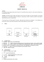
AXBB-010
Brand: Axxion Pages: 3

WGen3600cv
Brand: Westinghouse Pages: 79

SX100+
Brand: Electro-Voice Pages: 12

RD903600 Series
Brand: RIDGID Pages: 60

FG3005
Brand: Clarke Pages: 28

PDVD830
Brand: Lenox Pages: 23

Guardian 5500
Brand: Lafayette Pages: 7

GCRS-40-40 T4F
Brand: morse Pages: 34

UV-5R Series
Brand: Baofeng Pages: 20

PP14BT
Brand: Blaupunkt Pages: 162

CTO Series
Brand: Aqua Pages: 22

AA76100
Brand: De La Rosa Research Pages: 9

DVD9017
Brand: Reflexion Pages: 43

HTT-500
Brand: PowerTrunk Pages: 52

DRC99390
Brand: RCA Pages: 2

Portable DVD 180
Brand: Ingo Pages: 50

PS407
Brand: ACME Pages: 64

PDV 67003
Brand: Odys Pages: 63


