


page 26 — DCa25Usi 60 hz generaTor • operaTion anD parTs manUal — rev. #3 (07/19/11)
Output terMinal panel cOnnectiOns
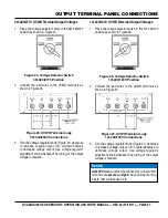
UvWo Terminal oUTpUT volTages
Various output voltages can be obtained using the UVWO
output terminal lugs. The voltages at the terminals are
dependent on the position of the
voltage selector switch
and the adjustment of the
voltage regulator Control
Knob.
Remember the voltage selector switch determines the
range of the output voltage. The voltage regulator (VR)
allows the user to increase or decrease the selected
voltage.
3Ø-240/139 UvWo Terminal output voltages
1. Place the voltage selector switch in the 3Ø 240/139
position as shown in Figure 19.
Figure 19. Voltage Selector Switch
3Ø-240/139V Position
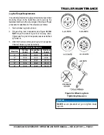
2. Connect the load wires to the UVWO terminals as
shown in Figure 20.
Figure 20. UVWO Terminal Lugs
3Ø-240/139V Connections
3. Turn the voltage regulator knob (Figure 21) clockwise
to increase voltage output, turn counterclockwise to
decrease voltage output. Use voltage regulator
adjustment knob whenever fine tuning of the output
voltage is required.
Figure 21. Voltage Regulator Knob
3Ø-208v/1Ø-120v UvWo Terminal output voltages
1. Place the voltage selector switch in the 3Ø 240/139
position as shown in Figure 22.
Figure 22. Voltage Selector Switch
3Ø-240/139V Position
2. Connect the load wires to the UVWO terminals as
shown in Figure 23.
Figure 23. UVWO Terminal Lugs
3Ø-208/1Ø-120V Connections Connections
NOTICE
To achieve a 3Ø 208V output the voltage selector switch
must be in the 3Ø-240/139 position and the voltage
regulator must be adjusted to 208V..
Summary of Contents for DCA5USI
Page 47: ...DCA25usi 60 hz Generator operation and parts manual rev 3 07 19 11 page 47 notes...
Page 50: ...page 50 DCA25Usi 60 hz Generator operation and parts manual rev 3 07 19 11 GENERATOR ASSY...
Page 52: ...page 52 DCA25Usi 60 hz Generator operation and parts manual rev 3 07 19 11 control box ASSY...
Page 54: ...page 54 DCA25Usi 60 hz Generator operation and parts manual rev 3 07 19 11 control box ASSY...
Page 62: ...page 62 DCA25Usi 60 hz Generator operation and parts manual rev 3 07 19 11 BATTERY ASSY...
Page 64: ...page 64 DCA25Usi 60 hz Generator operation and parts manual rev 3 07 19 11 Muffler Assy...
Page 66: ...page 66 DCA25Usi 60 hz Generator operation and parts manual rev 3 07 19 11 FUEL TANK ASSY...
Page 68: ...page 68 DCA25Usi 60 hz Generator operation and parts manual rev 3 07 19 11 ENCLOSURE ASSY...
Page 74: ...page 74 DCA25Usi 60 hz Generator operation and parts manual rev 3 07 19 11 RUBBER SEALS ASSY...
Page 79: ...DCA25usi 60 hz Generator operation and parts manual rev 3 07 19 11 page 79 notes...


