background image

26

1

2

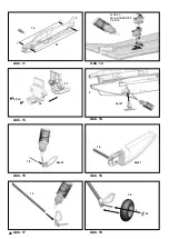
Abb. 11 


Abb. 12 


Abb. 13 


Abb. 14 


Abb. 15 


Abb. 16 


Abb. 17 


Abb. 18 


14

14

3

37

36

43

(2x)

3

36+37

18

18

13

38

39

40+41

40+41

2x Servo 
Nano-KARBONITE
# 6 5118


Summary of Contents for ParkMaster PRO

Page 1: ...LTIPLEX 2015 Version 1 0 24 29 48 49 21 4275 ParkMaster PRO Erhältliche Varianten Available versions Version disponible Varianti disponibili Variantes disponibles Ersatzteile Replacement parts Pièces de rechanges Parti di ricambio Repuestos Abbildungen Illustrations Illustrations Illnstrazioni Iiustraciónes vorgesehen für den MULTIPLEX Brushless Antrieb 33 2652 Designed for the MULTIPLEX brushless...

Page 2: ...Hersteller Zum Betrieb des Modells darf nur das von uns empfohlene Zubehör verwendet werden Die empfohlenen Komponenten sind erprobt und auf eine sichere Funktion passend zum Modell abgestimmt Werden andere Komponenten verwendet oder das Modell verändert erlöschen alle Ansprüche an den Hersteller bzw den Vertreiber Um das Risiko beim Betrieb des Modells möglichst gering zu halten beachten Sie folg...

Page 3: ... stets von einem Helfer sicher festgehalten werden Absturz durch Steuerfehler Kann dem besten Piloten passieren deshalb nur in sicherer Umgebung fliegen ein zugelassenes Modellfluggelände und eine entsprechende Versicherung sind unabdingbar Absturz durch technisches Versagen oder unentdeckten Transport oder Vorschaden Die sorgfältige Überprüfung des Modells vor jedem Flug ist ein Muss Es muss jedo...

Page 4: ...ns keinen Ersatz Tasten Sie sich also vorsichtig an die Grenzen heran Das Modell ist auf den von uns empfohlenen Antrieb ausgelegt kann aber nur einwandfrei gebaut und unbeschädigt den Belastungen standhalten Fernsteuerelemente im Modell sonstiges Zubehör Empfohlene Ausrüstung MULTIPLEX Empfänger ab RX 5 light M LINK Best Nr 5 5808 Dazu können Sie auch auf unsere telemetriefähigen M LINK Empfänger...

Page 5: ...itte der Bauanleitung heraustrennen Tuning Motorspant Der optional erhältliche Carbon Motorspant 33 2609 ist aus hochwertigem Kohlefaser Plattenmaterial ausgefräst und mit passgenauen Aluminium Gewindeeinsätzen versehen Beim Einbau dieses Spants beachten Sie bitte dass die 4 Justierschrauben für Seitenzug und Motorsturz nach den Einstellarbeiten mit Sicherungslack versehen werden 1 Vor dem Bau Prü...

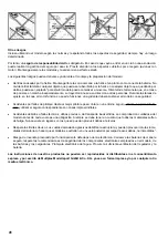
Page 6: ...halter 40 41 einkleben Abb 17 12 Räder montieren Die Räder 38 werden auf die Radachsen gesteckt und mit der Wellensicherung 39 gesichert Abb 18 Zum Montieren der Wellensicherungen 39 legen Sie eine wenig geöffnete Zange wie in Abb 19 auf den Tisch und drücken die Radachse 18 in die Wellensicherung Ist die Achse erst mal in der Sicherung lässt sich diese zum jus tieren verschieben Lassen Sie den Rä...

Page 7: ... Vorlage Baukastenbild Bau anleitung oder nach eigener Vorstellung aufgebracht 22 Propeller wuchten Der Propeller eines Modellflugzeuges muss gewuchtet werden um rund und vibrationsfrei zu laufen Die von uns ausgelieferten Propeller sind sehr eng toleriert können aber kleine Unwuchten enthalten Zum Wuchten empfeh len wir unser Propeller Wuchtgerät 33 2355 23 Propeller montieren Beim montieren des ...

Page 8: ...enzierung Fliegen Sie mit Halbgas 3 4 Rollen rechts bricht das Mo dell dabei nach rechts aus muss die Differenzierung grö ßer werden Falls es nach links gegen den Rollsinn aus bricht haben Sie zuviel Differenzierung eingestellt 33 Vorbereitungen für den Erstflug Für den Erstflug warten Sie einen möglichst windstillen Tag ab Besonders günstig sind oft die Abendstunden Vor dem ersten Flug unbedingt ...

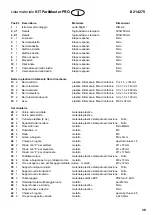
Page 9: ...band Pilzkopf Kunststoff 25 x 60mm 21 2 Klettband Velours Kunststoff 25 x 60mm 22 3 Folienscharnier 6er Baum Kunststoff gespritzt Fertigteil 23 4 Einkleberuderhorn Kunststoff gespritzt Fertigteil 24 4 Gestängeanschluß Metall Fertigteil Ø6mm 25 4 U Scheibe Metall M2 26 4 Mutter Metall M2 27 4 Inbus Gewindestift Metall M3 x 3mm 28 1 Inbusschlüssel Metall SW 1 5 29 2 Querrudergestänge m Z Metall Ø1 x...

Page 10: ... model may only be operated in conjunction with those accessories which we expressly recommend The recom mended components have undergone thorough testing are an accurate match to the model and ensure that it functions safely If you use other components or modify the model you operate it at your own risk and any claim under guarantee is invalidated To minimise the risk when operating the model ple...

Page 11: ...re that the model is always held securely by an assistant Crash caused by pilot error this can happen even to the best of pilots so it is essential to fly exclusively in a safe environment an approved model flying site and suitable insurance are basic essentials Crash caused by technical failure or unnoticed damage in transit or in the workshop A thorough check of the model before every flight is ...

Page 12: ...y result in the loss of the aircraft Please note we will not replace the model in such cases It is your responsibility to ap proach the airframe s limits gradually It is designed for the power system recommended in these instructions but is only capable of withstanding the flight loads if built exactly as described and if it is in an undamaged state Airborne radio control system components other a...

Page 13: ...cated at a point 110 120 mm aft of the wing root leading edge measured at the fuselage Note Please separate the pictorial pages from the centre of the building instructions before you start construction Tuning firewall The carbon firewall motor bulkhead 33 2609 is machined from high quality carbon fibre sheet material and is fitted with accurately made aluminium threaded inserts If you intend to i...

Page 14: ...h and make sure the glued joint is really sound Fig 14 11 Gluing the wheel axles to the undercarriage legs Glue the two wheel axles 18 in the axle brackets 40 41 Figs 15 16 Glue the two undercarriage legs 13 in the axle brackets 40 41 Fig 17 12 Fitting the wheels The next step is to slip the wheels 38 onto the wheel axles and secure them with the starlock washers 39 Fig 18 Fit the starlock washer ...

Page 15: ...ler motor or radio control system components this is left to your own discretion but we are unable to provide support in this case 21 Gilding the lily applying the decals The kit is supplied with two decal sheets 2 the individual name placards and emblems are already plotted Apply them to the model in the position shown in the kit box illustration or in an arrangement which you find pleasing 22 Ba...

Page 16: ...t the case adjust the sidethrust to correct the fault Repeat the test several times as any sidewind will tend to falsify the model s track 31 Downthrust Apply full throttle and fly the model straight and level until it arrives at your location so that you have a clear view of the model from one side Pull the aircraft up into a vertical climb it should continue to climb vertically and not fall away...

Page 17: ... foam Ready made CFRP strip 13 2 Undercarriage leg CFRP 10 x 1 5 x 144 mm 14 2 Fuselage longeron CFRP 3 0 x 1 0 x 743 mm 15 2 Wing spar CFRP 3 0 x 1 0 x 850 mm 16 1 Elevator spar CFRP 3 0 x 1 0 x 400 mm 17 2 Forward fuselage stiffener CFRP 3 0 x 1 0 x 120 mm 18 2 Wheel axle CFRP 2 5 Ø x 32 mm Small parts set 20 2 Hook and loop tape hook Plastic 25 x 60mm 21 2 Hook and loop tape loop Plastic 25 x 6...

Page 18: ...lisation dans un autre domaine est absolument interdite Pour tout dommage ou blessure sur des personnes ou des animaux résultant d une utilisation non conforme c est l utilisateur qui en porte la responsabilité et non le fabricant N utilisez votre modèle qu avec les accessoires conseillés Les composants accessoires conseillés sont testés sur leur fonctionnalité et compatibilité par rapport au modè...

Page 19: ...à ce que celui ci n aille jamais vers les personnes dans le cas ou le moteur venait à démarrer Lors de travaux de réglages pour lesquels le moteur est en marche ou peut démarrer il est impératif qu une tierce personne tienne votre modèle Crash suite à une erreur de pilotage cela peut arriver au meilleur pilote de ce fait il faut évoluer dans une zone sécurisée comme un terrain de modélisme par exe...

Page 20: ...ouver progressivement les limites de votre modèle Celui ci est adapté pour accueillir la propulsion que nous vous conseillons néanmoins que suite à un assemblage irréprochable et exempt de tout dommage afin de pouvoir résister aux contraintes Radiocommande dans le modèle équipement divers Equipement conseillé Récepteur MULTIPLEX à partir de RX 5 light M LINK Nr Com 5 5808 De plus vous pouvez égale...

Page 21: ...l arrière du modèle à partir du bord d attaque mesuré au niveau du fuselage Remarque Enlevez les pages comportant des images de la notice Support moteur Tuning Le support moteur 33 2609 disponible en option est réalisé dans une matière fibre carbone lamellé de grande qualité fraisé avec des écrous encastrés en aluminium Lors de l utilisation de ce support veillez à ce que les 4 vis d ajustages de ...

Page 22: ...vis 43 Il ne doit pas y avoir de colle dans les fentes de passage de train d atterrissage Fig 13 10 Mise en place et collage du support de train d atterrissage Adaptez les ouvertures afin que le support de train d atterrissage se mette correctement en place dans le fu selage puis collez le soigneusement et jointivement dans le fuselage Fig 14 11 Collage des axes de roues et jambe de train Collez l...

Page 23: ...e kit de propulsion sont parfaite ment adaptés entre eux et ont donnés d excellents résultats Si vous deviez utiliser un accu de propulsion régulateur moteur ou composant de radiocommande différent cela ne fait appel qu à votre appréciation Néanmoins un soutien de notre part ne sera plus possible 21 Un petit quelque chose pour l esthétique Pour cela vous trouverez deux planches de décalcomanies 2 ...

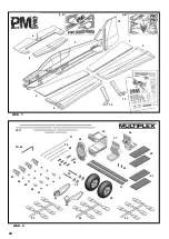
Page 24: ...24 Abb 1 Abb 2 9 8 3 10 7 5 6 4 11 12 14 17 27 42 31 30 29 33 34 32 35 37 36 20 21 43 13 38 18 41 40 22 22 22 23 26 25 24 27 39 2 A 2 B ...

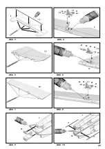
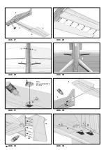
Page 25: ...25 Abb 3 Abb 4 Abb 5 Abb 6 Abb 7 Abb 8 Abb 9 Abb 10 9 16 26 25 23 24 27 9 10 27 24 23 25 26 10 6 7 26 25 23 24 27 35 3 17 3 17 35 ...

Page 26: ...26 1 2 Abb 11 Abb 12 Abb 13 Abb 14 Abb 15 Abb 16 Abb 17 Abb 18 14 14 3 37 36 43 2x 3 36 37 18 18 13 38 39 40 41 40 41 2x Servo Nano KARBONITE 6 5118 ...

Page 27: ...27 Abb 19 Abb 20 Abb 21 Abb 22 Abb 23 Abb 24 Abb 25 Abb 26 39 13 11 12 40 41 36 37 13 22 6 4 ...

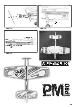
Page 28: ...28 Abb 27 Abb 28 Abb 29 Abb 30 Abb 31 Abb 32 Abb 33 Abb 34 3 6 5 4 29 3 8 31 30 22 10 Servo Nano KARBONITE 6 5118 ...

Page 29: ...29 Abb 35 Abb 36 Abb 37 motor RX 5 light M Link battery controller 110 120 33 2652 4x Servo Nano Karbonite ...

Page 30: ...ez du ballast après l atterrissage 30 Compensation de dérive Passez devant vous en plein gaz puis tirez sur la profon deur pour le faire monter à la verticale Dans cette position de vol votre modèle ne doit casser sa trajectoire ni d un côté ni de l autre Attention ne vous laissez pas induire en erreur par le vent 31 Piqueur moteur Passez devant vous en plein gaz de telle manière à pou voir le voi...

Page 31: ...rbone 13 2 Baguette de train CFK 10 x 1 5 x 144mm 14 2 Longerons de fuselage CFK 3 0 x 1 0 x 743mm 15 2 Longerons d aile CFK 3 0 x 1 0 x 850mm 16 1 Baguette de gouverne de profondeur CFK 3 0 x 1 0 x 400mm 17 2 Longeron de fuselage avant CFK 3 0 x 1 0 x 120mm 18 2 Axe de roue CFK Ø2 5 x 32mm Petit nécessaire 20 2 Velcro côté crochets Plastique 25 x 60mm 21 2 Velcro côté velours Plastique 25 x 60mm ...

Page 32: ...ente l utente del modello e non il costruttore Per l uso del modello è permesso utilizzare solo gli accessori da noi consigliati I componenti consigliati sono già collaudati e adattati al modello ai fini di un funzionamento sicuro Se si utilizzano altri componenti o se il modello viene modificato vengono a mancare tutti i diritti di garanzia del costruttore e o rivenditore Per mantenere basso il r...

Page 33: ...e dovuto ad errore di comando Può succedere anche al miglior pilota quindi far volare il modello solo in ambiente sicuro un terreno omologato per aeromodelli è una relativa sicurezza sono indispensabili Precipitazione dovuta ad errore tecnico o danni dovuti al trasporto o danni precedenti non conosciuti È obbli gatorio controllare attentamente il modello prima di ogni messa in volo Ma bisogna semp...

Page 34: ...sono comportare la perdita del modello Osservare quanto segue in tali casi non forniamo alcuna sostituzione Avvicinarsi con attenzione ai limiti Il modello è previsto per la motorizzazione da noi consigliata ma può resistere per fettamente e senza danni ai carichi solo se assemblato in modo perfetto Gli elementi radiocomandati nel modello altri accessori Dotazione cosigliata Ricevente MULTIPLEX a ...

Page 35: ... di filetti riportati in alluminio realizzati su misura Durante il montaggio di questa ordinata si prega di osservare che alle 4 viti di registro per il disassamento motore laterale e il disassamento motore verticale dopo gli inter venti di regolazione veine applicato il frenafiletti 1 Prima del montaggio Prima di iniziare a costruire il modello controllare il conte nuto della vostra scatola di mo...

Page 36: ...issaggio 39 poggiare sul tavolo una pinza leggermente aperta come da fig 19 sul tavolo e premere l asse 18 nella rondella di fissaggio Una volta che l asse è nel fissaggio lo si può spostare per essere regolato Lasciare del gioco di lato alle ruote in modo che possano essere girate senza problemi Fig 19 13 Applicare le carenature carrello Ora incollare le carenature carrello 11 12 Incollarle alla ...

Page 37: ...a tenere conto di alcune cose Stringere le viti dell ordinata motore è importante prima di far funzionare per la prima volte il motore controllare tutti gli avvitamenti e se necessario stringerli di nuovo Le viti di regolazione dell eliche traenti e del disassamento devono essere serrate in modo che l estremità delle viti poggi in modo sicuro sui supporti in materiale plastico Accuratezza durante ...

Page 38: ...inistra diminuirla 33 Preparazioni per il primo volo Per il primo volo si prega di aspettare un giorno possibil mente senza vento Particolarmente favorevoli sono in genere le ore serali Prima del primo volo eseguire assolutamente un test della ricezione Attenersi alle indicazioni del costruttore del vostro radiocomando Il pacco batteria della radio e l accumulatore di volo sono stati appena carica...

Page 39: ...Ø2 5 x 32mm Set minuteria 20 2 Velcro parte uncinata materiale plastico 21 2 Velcro parte stoffa materiale plastico 22 3 Cerniera elastica 6 pz materiale plastico stampato ad iniezione finito 23 4 Squadretta da incollare materiale plastico stampato ad iniezione finito 24 4 Raccordo rinvii metallo finito Ø6mm 25 4 Rondella a U metallo M2 26 4 Dado metallo M2 27 4 Grano a brugola metallo M3 x 3mm 28...

Page 40: ...el fabricante Para utilizar el modelo deben ser utilizados exclusivamente los accesorios recomendados por nosotros Lo componentes recomendados han sido probados y adaptados para garantizar el funcionamiento seguro del modelo Si se modifica el modelo o se usan componentes distintos ni el fabricante ni el distribuidor podrán ser responsabilizados Para mantener al mínimo el riesgo al utilizar el mode...

Page 41: ...dad Accidentes por fallos de pilotaje Hasta al mejor piloto le pasa Volar en un entorno seguro utilizar una pista autoriz ada y utilizar el seguro correspondiente son cosas imprescindibles Accidentes debidos a fallos técnicos daños previos o de transporte inadvertidos La comprobación cuidadosa del modelo antes de cada vuelo es una obligación Siempre se debe tener en cuenta que todos los materiales...

Page 42: ...stos casos no le ofreceremos ningún sustituto Por tanto sea muy cuida doso a la hora de explorar sus límites El modelo está diseñado para el propulsor que le recomendamos solo de este modo se podrá montar sin esfuerzo y soportar las cargas sin daños Elementos RC en el modelo Otros accesorios Equipo recomendado Receptor MULTIPLEX a partir de RX 5 ight M LINK Referencia 5 5808 También podría decidir...

Page 43: ...arallamas de carbono 33 2609 está realizada con fibra laminada de carbono de alta calidad y provista de las pertinentes incrustaciones roscadas de aluminio Al montar esta cuaderna por favor asegúrese de aplicar líquido fija tornillos en los cuatro tornillos de ajuste incidencia y ajuste lateral 1 Antes de comenzar el montaje Antes de comenzar el montaje compruebe el contenido de su kit Le serán mu...

Page 44: ...e encajan en los ejes de las ruedas y se fijan con ayuda de los clips circulares 39 Img 18 Para montar los clips circulares 39 ponga unos alicates que estén un poco abiertos sobre la mesa como se indica en la Img 19 y presione los ejes de las ruedas 18 contra los clips circulares Una vez que el eje esté en la fijación podrá desplazarlo para su ajuste Deje la suficiente holgura lateral en las rueda...

Page 45: ...355 23 Instalar la hélice Al montar la hélice junto al tensor y la tuerca del cono deberá tener en cuenta algunas cosas Apretar los tornillos de la cuaderna del motor Es importante que antes de poner en marcha el motor por primera vez compruebe todos los tornillos y los apriete si fuese necesario Las tornillos para regular las incidencias vertical y horizontal deben ser apretados de manera que los...

Page 46: ...enciación Si se va hacía la izquierda en el sentido del roll es que la diferenciación es demasiado grande 33 Preparativos al primer vuelo Para su primer vuelo espere siempre a un día en el que haga el menor viento posible A menudo las horas del atardecer son el mejor momento Antes del primer vuelo Es imprescindible hacer una prueba de alcance Cíñase para ello a las indicaciones del fabricante de s...

Page 47: ...20mm 18 2 Eje de las ruedas Fibra de carbono Ø2 5 x 32 mm Accesorios 20 2 Velcro rugoso Plástico25 x 60 mm 21 2 Velcro suave Plástico25 x 60 mm 22 3 Bisagras de hoja simulada Plástico inyectado Pieza prefabricada 23 4 Adaptador Plástico inyectado Pieza prefabricada 24 4 Retén de varilla Metal Pieza prefabricada Ø6 mm 25 4 Arandela Metal M2 26 4 Tuerca Metal M2 27 4 Prisionero Allen Metal M3 x 3 mm...

Page 48: ...48 ...

Page 49: ...49 ...

Page 50: ... teilig Decals 2 sheets 2A 2B 2 22 4822 Rumpf mit Fahrwerksverkleidungen Fuselage with undercarriage cover Rumpf Fahrwerksverkleidung links rechts Fuselage Undercarriage cover L H R H 3 11 12 1 2 22 4823 Tragflächen Wings Tragfläche links rechts Querruder links rechts Wing L H R H Aileron L H R H 4 5 6 7 2 2 22 4854 Kleinteilesatz Small parts kit 68 3112 5 St 68 3112 5 St 70 3206 2 St 70 3455 2 St...

Page 51: ...6 22 x3 31 Seitenrudergestänge m Z Pre formed rudder pushrod Tringle pour dérive avec embout Z 30 Höhenrudergestänge m Z Pre formed elevator pushrod Tringle pour profondeur avec embout Z 32 Motorspant Firewall Support moteur 34 Schraube Motorspantbefestigung M3x12mm Firewall attachment screw Vis de fixation support moteur x2 35 Motorspanthalter Motor mount Support moteur 73 3190 2 St Leichtrad Ø 5...

Page 52: ...52 MULTIPLEX Modellsport GmbH Co KG Westliche Gewerbestrasse 1 D 75015 Bretten Gölshausen www multiplex rc de Anleitung ParkMaster PRO 94 4820 20150415 BEDO Irrtum und Änderungen vorbehalten MULTIPLEX ...

Reviews: