


Optima D Receiver Specifications & Features
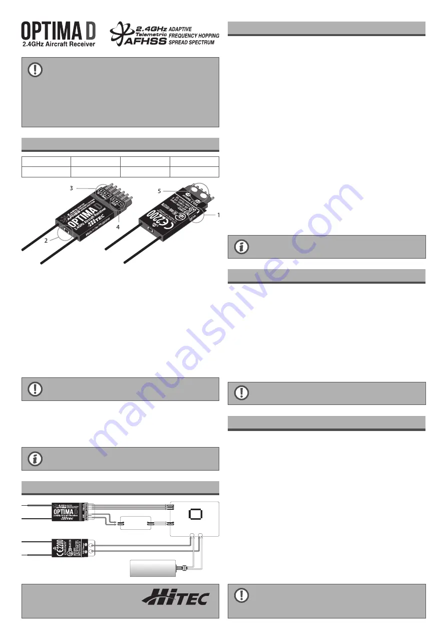
Optima D Drone Connection Diagram
How to Link (ID-Set)
Signal Mode Change ( PPM, S-Bus )
FAIL-SAFE and Hold Mode Setup
1. The receiver antenna should not be placed near the engine, metal parts, or
high current batteries.
2. The receiver Antenna should not get damaged. To prevent antenna dama-
ge, do not install the antenna near the sharp edge or bend it more than
90 degree in angle.
3. Use a Velcro or think double sided tape to install to absolve the shock
during the operation.
4. When LED indicator irregularly blinks, indicates unstable frequency environ-
ment, stop operating and look for the possible cause of problems.
Receiver Model
Size
Weight
Stock Number
Optima D
35 x 16.8 x 5mm
4.1g
111054
1. LED:
- Shows current status or set up status.
2. LINK Button:
- For Link(ID-Set) and set functions.
3. BUS signal output:
- Optima D provides PPM, S-Bus signal. User have to select PPM or S-Bus system
according to Flight Control system.
4. RSSI signal output:
- Via RSSI, communication sensitivity can be seen through OSD.
5. Voltage Sensor input:
- Main power can be checked by this tap
- User need to have soldering direct to here to check battery voltage (0.5V to 35V)
After soldering job, please cover soldering spot to prevent explosion or catch
the fire by circuit short.
In order to prevent accident by incorrect operation, please check all functions
without props.
- The FAIL-SAFE settings should be checked every time before you run the
engine/motor.
- This product is designed to be used as a R/C hobby product and should be
operated under local regulation.
Servo manufacturer will specify maximum voltage of their servo model.
Please refer each servo’s specification.
When you purchase a radio set that Transmitter and receiver include together in the box,
each device are linked already from the factory. If you purchase extra receivers or transmitter,
you need to have Link with current your device together.
Before ‘Link’ process, please check correct installation refer to above Drone Connection Diagram.
AURORA 9
1. Press and hold the button on the module, and turn on the transmitter*
For Aurora 9, once connect to module, press Link button in the module and turn on the
transmitter.
Press Transmit “Yes” in the Aurora 9 screen and then release Link button.
2. Press Link button in the Receiver and turn on the Receiver. Once Receiver power is on,
release Link button.
After release Link button, LED will turn Blue and entered Scan mode.
3. Once connection is completed, Red LED will be on in the module. After that BLUE LED will
be blinking.
At the same time BLUE LED in the Receiver also will be blinking. Now Connection is completed
4. Turn off and On both transmitter and receiver together, Beep sounds will be spoken 4 times.
This sound also shows that connection is completed.
AURORA 9X, FLASH Series
1. Turn On the Transmitter.
2. Select ‘Spectra’ in the System menu of Transmitter.
3. Select RX type as “Opti&Mini”. Select ‘Binding’ and press ‘YES’.
4. Press Link button in the Receiver and turn on the Receiver. LED will turn Blue and entered
Scan mode
5. Once Link is completed, Transmitter screen will be changed to the next step.
6. Turn Off/On the Receiver power and check the operation. Press ‘Finish’ on the radio to
complete the Link.
Optima D provides PPM and S-BUS signal. User can choice one of PPM or S-BUS according
to their FC (Flight Control).
1. Turn off the transmitter during this process
2. Press “Link” button of Optima D and turn on the Power.
3. Once BLUE LED blink 5 times, release Link Button.
Once release Link Button, current bus type will be shown.
4. If BLUE LED is blinking 2 times- this is PPM Mode
If BLUE LED is blinking 3 times – this is S-BUS Mode
Once press Link, Mode will be changed.
5. Once signal mode is selected, press and hold Link Button about 3 seconds and release.
LED will be blinking rapidly. This is confirmation sign.
6. Turn Off/ On the receiver to check suitable signal Mode.
FAIL-SAFE point you previously stored in the FAIL-SAFE set-up. Make sure you set the FAIL-SA-
FE function properly.
If FAIL-SAFE has not been activated, the signal will switch off after the HOLD period of one second.
This means that the servos become “soft” and remain in their last commanded position under no load
(this may equate to full-throttle!), until a valid signal is picked up again.
In the interest of safety, we recommend that the FAIL-SAFE function should always be activated,
and the FAIL-SAFE settings should be selected so as to bring the model to a non-critical situation
(e.g. motor idle / electric motor OFF, control surfaces neutral, airbrakes extended, aero-tow
release open, etc.).
1. Turn On the transmitter and receiver
2. Check the correct operation and place control stick or control toggle of transmitter to fail-safe
position.
3. Press and Hold Link button in the receiver in 6 seconds.
BLUE LED will be blinking start slowly and then blinking rapidly.
4. Once BLUE LED change to solid BLUE, Fail Safe is successfully completed.
5. Please turn off the transmitter to check the operation.
Deactivate Fail Safe
During the set Fail-Safe (please refer to above Fail Safe set up phase No.3), once LED start
blinking, please press Link Button ‘one time’ to set Deactivate Fail Safe function.
Operation Voltage
- 4.8V~8.4V (BEC from ESC can be used)
Compatibility
- Optima D is using Hitec AFHSS 2.4GHz system, all Hitec radios can control Optima D Receiver.
Please place transmitter and receiver together less than 1 meter distance to
prevent signal interrupt
Instruction manual
MULTIPLEX Modellsport GmbH & Co.KG
Westliche Gewerbestr. 1
75015 Bretten · Germany
www.multiplex-rc.de
Multiplex Service: +49 (0) 7252 - 5 80 93 33
Top
Bottom
Groud
+5v
PPM or S-Bus
VBAT
GND
Flight Controller
OSD
RSSI
Groud
TX
RX
RX
TX
V-
V+
Power
Battery