Multiplex Blizzard 21 4233 Building Instructions Download Page 24

www.modellmarkt24.ch

24

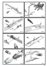
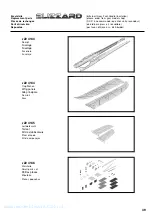
the ailerons. Connect the pre-formed aileron pushrods 

28

 to the

outermost hole in the servo output arms. At the other end slip the
wire pushrod 

28

 through the barrel 

25

 of the swivel connector.

Set the servos and the ailerons to centre, and tighten the
grubscrews 

26

 in the barrels to secure the pushrods.

Fig. 29

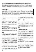
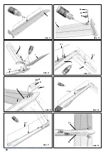
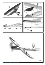
21. Concealing the aileron servos

Since the wings are extremely thin, the servos are installed flush
with the top surface of the airfoil. For aerodynamic reasons (and
to improve appearance) they should be covered using the thin,
rigid, self-adhesive stickers 

26

.

Fig. 30

22. Aileron pushrod fairings

The servo fairings 

44 + 45

 can now be fitted; they further improve

aerodynamic efficiency as well as protecting the aileron pushrods
(actually it is the servo gears which need protection).

Fig. 31

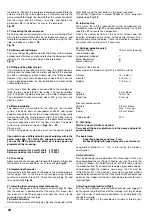
23. Fitting out the glider version

If you intend to fly your Blizzard at the slope, the simple option is
just to launch the model with the motor switched off; this provides
you with an emergency ‘get-you-home’ aid if the lift drops dead.
However, if you wish to make good use of weak lift, or if you are
simply a dedicated glider fan, the installation of a motor will be
unacceptable to you.

In this case attach the glider nose-cone 

42

 to the fuselage by

fitting the two screws 

33

 from the inside. The receiver battery

(e.g. # 16 6052) should be installed in the motor compartment.
The completed model will weigh about 200 g less than the
electric version.

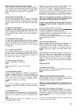
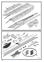
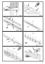
24. Motor installation

Two power sets are available for the Blizzard: the standard
system, # 33 2639, offers an input power of 280 W, and is quite
powerful enough for a brisk style of flying. However, things really
start moving with the Tuning power system, # 33 2643, with an
input power of 470 W. In the latter case the pilot should certainly
have prior experience with fast ‘full-house’ models. The power
systems are installed as shown in 

Figs. 33 + 34

.

Please note:
For the Tuning power system you must use the spacer ring 

43

.

If you wish to use a different motor, you should stay within the
power range 250 - 500 Watts. We strongly recommend that
you use the MPX spinner and driver as it looks good and
promotes efficient cooling.

Spinner and driver for 4 mm Ø shaft    # 73 3501
Spinner and driver for 5 mm Ø shaft    # 73 3502
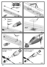
25. The canopy

Apply cyano to the canopy latch tongues 

23

 and push them into

the sockets in the canopy 

12

 as far as they will go. 

Fig. 35

26. Assembling the model

Connect the green M6 socket in the wing to the matching plug in
the fuselage, then fix the wing to the fuselage using the two
countersunk plastic screws 

31

. Check that everything fits and

lines up correctly. 

Fig. 36

27. Installing the receiving system components

The system components are installed as shown in 

Fig. 37

. Note

that the receiver is positioned aft of the wing. This means that
the leads must be long enough to enable the servos to be
connected outside the fuselage.

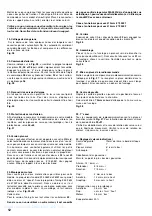
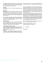
28. Centre of Gravity

Set the correct Centre of Gravity by adjusting the position of the

flight battery and the trim ballast in the ballast chamber.
The correct CG position is around 

70 mm

 aft of the wing root

leading edge. 

Fig. 38

29. Initial test-run

We assume that all the radio control system components are
installed as shown in 

Fig. 37

, and connected correctly. Use Velcro

tape 

20 + 21

 to secure the components.

Check the neutral position of the control surfaces and the
direction of rotation of the servos. All the control systems must
operate freely, without binding. Check the direction of rotation of
the motor shaft, and reverse it if necessary.

30. Settings (guideline only!):

Centre of Gravity:

70 mm aft of the wing

root leading edge
Longitudinal dihedral:

Motor downthrust:

Motor sidethrust:

Control surface travels:
Measured at the broadest chord of the control surfaces

Ailerons:

14 / 6 mm +/-

Elevator:

5 / 5 mm +/-

Rudder:

7 / 5 mm +/-

Flaps:

2 mm down

Spoilers:

12 mm up

Snap-flap:

2 mm up

Elevator compensation
Spoilers

0.5 mm ‘down’

Flap

max. 1 mm ‘up’

Power

0.5 mm ‘down’

Expo, elevator:

30%

31. Test-flying:
Wait for a day with little or no wind.
Carry out all the basic adjustments in the peace and quiet of
your workshop!

The basic rules:

Snap-flaps negative and max. 2 mm
No speed flying with flaps deployed (i.e. neutral only)

Longitudinal dihedral = 1°; this is pre-set by the model’s
construction

Centre of Gravity:

Start by balancing the model within the stated range. Once you
have completed the test-flying schedule, you can fine-tune the
setting as follows: fly straight and level at half-throttle, and roll
the model inverted. If you now have to apply a great deal of ‘down’
to hold level flight, the model is nose-heavy; the CG must be
shifted further aft. If the machine climbs whilst inverted, without
requiring elevator correction, the CG is too far aft. When balanced
correctly, the model will require slight down-elevator for level
inverted flight.

Correcting straight and level flight:

First the static balance: hold the model inverted, and support it
by the spinner and the tail end of the fuselage: with the fuselage
level, the wings should remain horizontal. If not, add ballast to
the lighter wingtip.
On the next flight, fly the aeroplane at minimum throttle (just

www.modellmarkt24.ch

Summary of Contents for Blizzard 21 4233

Page 1: ...r Tuning 33 2643 F GB D E I Bauanleitung 3 8 Notice de construction 9 14 Building instructions 15 26 Instruzioni di montaggio 27 32 Instrucciones de montaje 33 38 Ersatzteile Replacement parts Pièces de rechanges Parti di ricambio Repuestos 39 40 Copyright by MULTIPLEX 2008 Version 1 2 www modellmarkt24 ch ...

Page 2: ...he motor control on the transmitter is set to OFF When the model is switched on ready to fly take care not to touch the propeller Keep well clear of the propeller disc too and ask spectators to stay back Allow the motor to cool down after each flight You can check this by carefully touching the motor case with your finger The temperature is correct when you can hold your finger on the case without...

Page 3: ...Gefahren hin Zusätzlich zum Modell Blizzard erforderlich MULTIPLEX Fernsteuerelemente für das Modell Blizzard Empfänger RX 7 SYNTH IPD 35 MHz A Band Best Nr 5 5880 oder Empfänger RX 7 SYNTH IPD 35 MHz B Band Best Nr 5 5881 alternativ 40 41MHz Best Nr 5 5882 Servo Nano Karbonite 2 x erforderlich 2x Querruder Best Nr 6 5118 Servo Nano S 1 2 x erforderlich 1x Höhe 1x Seite Best Nr 6 5120 ggf Trennfil...

Page 4: ... nicht aus Styropor Daher sind Verklebungen mit Weißleim Polyrurethan oder Epoxy nicht mög lich Diese Kleber haften nur oberflächlich und platzen im Ernstfall einfach ab Verwenden Sie nur Cyanacrylat Sekundenkleber mittlerer Viskosität vorzugsweise unser Zacki ELAPOR 59 2727 der für ELAPOR Partikelschaum optimierte und angepasste Sekundenkleber Bei Verwendung von Zacki ELAPOR können Sie auf Kicker...

Page 5: ...er Torsionsfestigkeit werden auf der Ober und Unterseite Diagonalgurte 11 9 in Form einer Fischgräte eingeklebt Führen Sie diese Maßnahme sehr sorgfältig durch verkleben Sie auch die Knotenpunkte zum obe ren und unteren Tragflächengurt 11 4 11 3 Die Gräten lassen sich besser einkleben wenn Sie diese vorbiegen Abb 24 25 Fertigstellung der Tragfläche 17 Tragflügelabdeckung Unterhalb der Tragflächena...

Page 6: ...ten ist vorgegeben Seitenzug 0 Ruderausschläge An der tiefsten Stelle am Ruder gemessen Querruder 14 6 mm Höhenruder 5 5 mm Seite 7 5 mm Flap 2 mm nach unten Spoiler 12 mm nach oben Snapflap 2 mm nach oben Kompensation ins Höhenruder Spoiler 0 5 mm tief Flap knapp 1 mm hoch Motor 0 5 mm tief Expo Höhe 30 31 Einfliegen Warten Sie einen windstillen oder windarmen Tag ab Machen Sie alle Voreinstellun...

Page 7: ...X Produkte sind von erfah renen Modellfliegern aus der Praxis für die Praxis gemacht Fliegen Sie verantwortungsbewusst Anderen Leuten dicht über die Köpfe zu fliegen ist kein Zeichen für wirkliches Können der wirkliche Könner hat dies nicht nötig Weisen Sie auch andere Piloten in unser aller Interesse auf diese Tatsache hin Fliegen Sie immer so dass weder Sie noch andere in Gefahr kommen Denken Si...

Page 8: ...ewindestift Metall M3 x 3mm 27 1 Inbusschlüssel Metall SW 1 5 28 2 Querrudergestänge m Z Metall Ø1 x 60mm 29 1 V Höhenrudergestänge Metall Ø1 x 115 mm 30 2 Höhenrudergestänge m Z Metall Ø1 x 145mm 31 2 Senkschraube Tragfläche Kunststoff M5 x 20mm 32 2 Mutter Flügelgegenlager Metall M5 33 2 Schraube Seglernase Metall M3 x 16mm 34 1 Schraube Trimmschachtdeckel Metall 2 2 x 6 5mm 35 3 Trimmgewicht fü...

Page 9: ... et l utilisation correcte nous déclinons toute responsabilité concernant ces dangers Equipements nécessaires pour votre modèle Blizzard Eléments de radiocommunication pour votre modèle Blizzard Récepteur MULTIPLEX RX 7 Synth IPD 35 MHz Bande A Nr Com 5 5880 ou Récepteur MULTIPLEX RX 7 Synth IPD 35 MHz Bande B Nr Com 5 5881 alternative 40 41Mhz Nr Com 5 5882 servos Nano Karbonite nécessaire 2x 2x ...

Page 10: ...e indiqué sur la Fig 07 Eliminez au préalable le surplus de bras de levier des palonniers à l aide d une pince coupante et coupez les câbles de commande des servos au niveau du connecteur afin de pouvoir y souder une rallonge 300mm Veillez à isoler les zones de soudures avec de la gaine thermo 6 Assemblage du fuselage Ajustez les deux parties du fuselage puis si tout se place correctement collez l...

Page 11: ...ui n a aucune utilité Du fait que les longerons s adaptent parfaitement dans les ouvertures les accueillants l excédant de colle sera chassé ce qui aura pour effet que celle ci séchera rapidement Si vous faite une erreur à ce niveau la vous n arriverez pas à placer le longeron dans la bonne position avant que la colle n ai durcie Attention il est possible que le longeron s enfonce plus loin que le...

Page 12: ...sion électrique 24 Montage du moteur Nous avons prévu deux motorisations possibles pour votre modèle La propulsion standard 33 2639 de 280W vous permet déjà un vol assez speed Avec la propulsion Tuning 33 2643 de 470W cela décoiffe vraiment Dans ce dernier cas il est fortement conseillé que le pilote ai une bonne expérience avec des modèles rapides 3 axes L assemblage se fait comme indiqué sur les...

Page 13: ...tandard trimmez votre modèle pour que celui ci effectue un vol lent droit puis mettez plein gaz votre modèle doit prendre une faible pente ascendante Différentiel d aileron Volez 3 4 tonneaux à droit en mi puissance Si votre modèle sort de la trajectoire à droite il faut augmenter la valeur du différentiel Dans le cas contraire la valeur est trop grande réduisez la 32 Un petit quelque chose pour l...

Page 14: ...bus Métal SW 1 5 28 2 Tringle aileron avec embout en Z Métal Ø1 x 60mm 29 1 Tringle empennage en V Métal Ø1 x 115mm 30 2 Tringle profondeur avec embout en Z Métal Ø1 x 145mm 31 2 Vis à tête fraisée fixation de l aile Plastique M5 x 20mm 32 2 Ecrou fixation d aile Métal M5 33 2 Vis nez du fuselage Métal M3 x 16mm 34 1 Vis vis du couvercle de trim Métal 2 2 x 6 5mm 35 3 Ballast pour version électriq...

Page 15: ...ts we are obliged to take this opportunity to point out these hazards and to emphasise your personal responsibility Additional items required for the Blizzard MULTIPLEX receiving system components for the Blizzard RX 7 Synth IPD receiver 35 MHz A band Order No 5 5880 or RX 7 Synth IPD receiver 35 MHz B band Order No 5 5881 alternatively 40 41 MHz band Order No 5 5882 Nano Karbonite servo 2 x requi...

Page 16: ...uctors Tin the individual contacts of the M6 plug Slip a piece of heat shrink sleeve over each wire and solder the wire ends to the contacts in the arrangement shown in Fig 4 Slip the sleeves over the soldered joints and shrink them in place using a heat gun or similar Note that the M6 plug and socket should be fitted together before you carry out the soldering this ensures that the contacts take ...

Page 17: ...t in the wing c Lay the wing down flat d In one swift process press the spar into the spar slot as far as it will go e Immediately wipe off excess glue where it is squeezed out of the channel f If necessary flex the wing away from the spar slightly across the chord and apply more glue Fig 21 16 Additional wing reinforcements The bottom spar cap 11 3 can now be glued to the underside of the wing la...

Page 18: ...www modellmarkt24 ch 18 7 8 2 6 4 4 5 15 40 25 26 31 32 36 35 34 29 30 16 44 45 24 28 27 10 9 14 Abb 1 Abb 2 34 41 20 21 11 22 23 13 43 33 42 www modellmarkt24 ch ...

Page 19: ...www modellmarkt24 ch 19 4 Abb 03 Abb 04 Abb 05 Strecker M6 grün 8 5213 Abb 06 Abb 07 3 Abb 08 Abb 09 3 4 Abb 10 3 4 13 4 4 3 4 14 11 5 22 40 11 8 32 32 40 14 www modellmarkt24 ch ...

Page 20: ...www modellmarkt24 ch 20 5 11 2 26 Abb 12 Abb 13 8 Abb 15 Abb 11 Abb 14 Abb 17 Abb 16 Abb 18 7 8 3 4 3 7 11 1 11 1 8 4 41 35 34 14 11 7 30 30 25 24 8 11 6 www modellmarkt24 ch ...

Page 21: ...www modellmarkt24 ch 21 Abb 20 Abb 21 Abb 22 Abb 23 Abb 24 Abb 25 Abb 26 11 4 15 Abb 19 6 5 9 5 6 10 29 5 6 6 x 11 9 4x 11 9 5 6 11 3 5 www modellmarkt24 ch ...

Page 22: ...ch 22 Abb 27 Abb 28 Abb 29 Abb 30 Abb 31 Abb 32 Abb 34 Abb 33 28 36 43 Antriebssatz Powerset 16 42 45 Buchse M6 grün 8 5214 Antriebssatz Powerset TUNING 33 2643 26 25 24 Oberseite Top side 33 33 2639 www modellmarkt24 ch ...

Page 23: ...www modellmarkt24 ch 23 Abb 35 Abb 36 Abb 37 Abb 38 Motor 31 70 mm 2 1 12 23 Abb 39 12 Controler Akku Rx www modellmarkt24 ch ...

Page 24: ...hing plug in the fuselage then fix the wing to the fuselage using the two countersunk plastic screws 31 Check that everything fits and lines up correctly Fig 36 27 Installing the receiving system components The system components are installed as shown in Fig 37 Note that the receiver is positioned aft of the wing This means that the leads must be long enough to enable the servos to be connected ou...

Page 25: ...ons shown in the kit box illustration or in an arrangement which you find pleasing 33 Safety Safety is the First Commandment when flying any model aircraft Third party insurance should be considered a basic essential If you join a model club suitable cover will usually be available through the organisation It is your personal responsibility to ensure that your insurance is adequate powered model a...

Page 26: ...ket head grubscrew Metal M3 x 3 mm 27 1 Allen key Metal 1 5 mm A F 28 2 Aileron pushrod one Z bend Metal 1 Ø x 60 mm 29 2 V tail pushrod Metal 1 Ø x 115 mm 30 2 Elevator pushrod one Z bend Metal 1 Ø x 145 mm 31 2 Countersunk wing retainer screw Plastic M5 x 20 mm 32 2 Nut wing retainer plate Metal M5 33 2 Screw glider nose cone Metal M3 x 16 mm 34 1 Screw trim compartment cover Metal 2 2 x 6 5 mm ...

Page 27: ...o Blizzard sono ulteriormente necessari Componenti RC per il modello Blizzard Ricevente RX 7 SYNTH IPD 35 MHz banda A Art nr 5 5880 oppure Ricevente RX 7 SYNTH IPD 35 MHz banda B Art nr 5 5881 in alternativa 40 41 MHz Art nr 5 5882 Servo Nano Karbonite necessari 2 pezzi 2x alettoni Art nr 5 5118 Servo Nano S necessari 1 2 pezzi 1x elevatore 1x direzionale Art nr 6 5120 eventualmente cavo con filtr...

Page 28: ...alterata la posizione dei contatti Incollare infine la spina M6 nel controsupporto 40 ed inserire i dadi 32 nelle sedi previste Colori dei cavetti con prolunghe UNI rosso rosso nero marrone giallo arancione 4 Fusoliera parte interna Cominciare con il semiguscio fusoliera 4 Tagliare su misura il rinforzo interno 11 8 e incollarlo con colla ciano Incollare il gancio di chiusura 22 nella sede previst...

Page 29: ...ala 17 Rivestimento alare centrale Con carta vetrata togliere da sotto il rivestimento alare 15 i pallini dalla superficie d incollaggio incollare infine il rivestimento con colla ciano Fig 26 18 Installare i servi e la presa M6 Posizionare in via provvisoria i servi Tagliare su misura i cavetti e posizionarli assieme alla presa M6 come indicato in Fig 27 Attenzione Controllare ancora una volta la...

Page 30: ...a velocità elevate con i flap abbassati solo posizione neutrale Con questo modello l incidenza di 1 è già predisposta Baricentro Per il primo volo bilanciare il modello con il baricentro indicato Per una regolazione precisa volo orizzontale a metà gas girare il modello a testa in giù Se si deve picchiare molto per tenere il modello in volo orizzontale spostare il baricentro indietro Se a testa in ...

Page 31: ...tere in pericolo i colleghi modellisti e gli spettatori Si prenda in considerazione che anche il migliore radiocomando può essere soggetto in ogni momento ad interferenze esterne Anche anni d esperienza senza incidenti non sono una garanzia per il prossimo minuto di volo Noi il Suo team MULTIPLEX Le auguriamo tanta soddisfazione e successo nella costruzione e più tardi nel far volare questo straor...

Page 32: ... 2 Rinvio per alettoni con Z metallo Ø1 x 60mm 29 1 Rinvio per elevatore a V metallo Ø1 x 115mm 30 2 Rinvio elevatore con Z metallo Ø1 x 145mm 31 2 Vite a testa svasata ala materiale plastico M5 x 20mm 32 2 Dado controsupporto alare metallo M5 33 2 Vite punta fusoliera aliante metallo M3 x 16mm 34 1 Vite coperchio vano zavorra metallo 2 2 x 6 5mm 35 3 Zavorra di bilanciamento per elettrico sfera a...

Page 33: ...lmente acerca de estos peligros Además del modelo Blizzard necesitará Componentes RC MULTIPLEX para el modelo Blizzard Receptor RX 7 SYNTH IPD 35 MHz Banda A Referencia 5 5880 o Receptor RX 7 SYNTH IPD 35 MHz Banda B Referencia 5 5881 como alternativa 40 41MHz Referencia 5 5882 Servo Nano Carbonita necesitará 2 2 x alerones Referencia 6 5118 Servo Nano S necesitará 1 2 1 x Prof 1 x Direc Referenci...

Page 34: ...desde el interior contra el revestimiento 13 Img 09 8 Montar el revestimiento trasero del fuselaje También deberá lijar la zona de pegado para que desaparezcan los granitos Unte la superficie con cianocrilato alinee correctamente el revestimiento 14 y siga presionando hasta que fragüe el pegamento Img 10 9 Preparar los empenajes 7 8 Haga practicables las superficies de mando timones dejando un 1 m...

Page 35: ...y pegue el refuerzo superior 11 4 Es muy recomendable que doble previamente los refuerzos en la zona de los marginales Img 23 Como medida especial para aumentar la resistencia ante la torsión se pegarán en el extradós y en el intradós refuerzos diagonales 11 9 con forma de espina de pescado Sea muy cuidadoso con este punto pegue también los puntos donde se unen los refuerzos superiores e inferiore...

Page 36: ...que Incidencias del ala 1 Incidencia vertical del motor 6 hacia abajo Incidencia lateral 0 Recorridos de las superficies de mando Recorridos de los timones en su deflexión máxima Alerones 14 6 mm Timón de profundidad 5 5 mm Dirección 7 5 mm Flap 2 mm hacia abajo Spoiler 10 mm hacia arriba Snapflap 2 mm hacia arriba Compensación en profundidad Spoiler 0 5 mm abajo Flap corto 1 mm arriba Motor 0 5 m...

Page 37: ...práctica de experimentados pilotos de radio control Vuele responsablemente Realizar pasadas por encima de las cabezas de la gente no es una demostración de saber hacer los que realmente saben no necesitan hacer eso Llame la atención a otros pilotos por el bien de todos si se comportan de esta manera Vuele siempre de manera que no se ponga nadie en peligro ni a Usted ni a otros Recuerde que hasta e...

Page 38: ...al Ø1 x 60mm 29 1 Varilla profundidad en V Metal Ø1 x 115 mm 30 2 Varilla de profundidad con forma de Z Metal Ø1 x 145mm 31 2 Tornillo cab Avellanada Alas Plástico M5 x 20mm 32 2 Tuerca encaje ala Metal M5 33 2 Tornillo morro velero Metal M3 x 16mm 34 1 Tornillo tapa de lastre Metal 2 2 x 6 5mm 35 3 Contrapeso para versión eléctrica Bola de acero 9g Ø13 mm 36 2 Adhesivo tapa servo superior Plástic...

Page 39: ...ani di coda Kit de empenajes 22 4146 Kleinteile Small parts set Petites pièces Minuteria Piezas pequeñas Ersatzteile bitte bei Ihrem Fachhändler bestellen Replacement parts please order from your model shop Pièces de rechanges S V P à ne commander que chez votre revendeur Parti di ricambio da ordinare presso il rivenditore Repuestos por favor diríjase a su distribuidor www modellmarkt24 ch ...

Page 40: ...atz mit Kabinenhaube pièces plastiques avec verrière Plastic parts set incl canopy Parti in materiale plastico con capottina piezas de plástico con cabina Kleber Empfehlung Recommended adhesive Colle conseillée Colla cnsigliata cola recomendada 59 2727 Zacki ELAPOR Ersatzteile bitte bei Ihrem Fachhändler bestellen Replacement parts please order from your model shop Pièces de rechanges S V P à ne c...

Reviews: