Basket Fan
4 | ENGLISH (US)
Original instructions
INS00131-A
Verify that the structure from which the fan is suspended can carry the weight
of the fan.
Make sure that the fan is suspended rigid enough, to prevent the fan from
swaying or shaking as a result of the forces generated by the fan.
Condensate drain holes
The fan motor has drain holes to allow condensation that may form inside the
motor to leave the motor. After installation, the drain hole at the lowest point
of the motor must be open, the other drain holes must be closed.
Spare condensate drain plugs are supplied with the fan. Keep all the drain
plugs as they must be temporarily reinserted in the open drain holes during
wet cleaning.
Illustration 3:
Condensate drain plug
WARNING
The fan must be installed with the lowest moving part at least
9ft (2.7m) above floor grade level.
4.2
Electrical
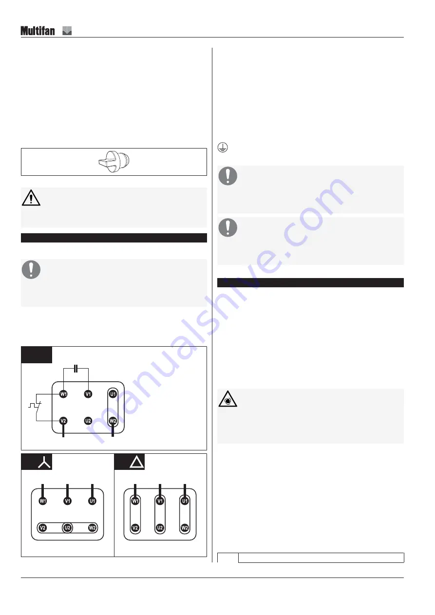
Wiring diagrams
NOTICE
Electrical connection must be carried out by a qualified electri-
cian. Electrical connections must be made in accordance with
local regulations.
Check the rating plate and verify that this fan is suitable for the available
power supply.
For 3~ fan motors: check that STAR / DELTA is properly configured on the
terminal block.
L1
N / L2
1~
AA
US
TB
L1
L2
L3
3~
3~
L1
L2
L3
AB03 AB04
AB01 AB02
NOTICE! STAR is for HIGH voltage / DELTA is for LOW
voltage
Control
This fan is supplied without a control or control system. A control or a control
system must be provided for operation of the fan.
Isolator
This fan is supplied without an electrical isolator. An electrical isolator must be
provided to facilitate safe maintenance and troubleshooting.
Grounding
The fan must be grounded. Ground the fan according to local
regulations.
NOTICE
Overcurrent protection
The use of an individual separate overcurrent protective device per
fan is highly recommended.
NOTICE
Overload protection
The use of an individual separate overload protective device (Motor
Protective Circuit Breaker) per fan is highly recommended.
4.2.1
Thermal protection
1~ fan motor thermal protection
Thermal detectors are built-in standard in 1~ fan motors. Thermal detectors
are of the thermostat type TB: thermostat opening on increase of
temperature.
In 1~ fan motors, the thermostat (TB) is by default wired in series with the
phase (L) of the supply. The motor is as such self-resetting: when the motor
overheats, the thermostat will switch off the motor automatically and once the
motor has cooled down, the motor will start automatically again.
The presence of the text “Thermally Protected” on the rating plate and/or
datasheet indicates that thermal protection is built-in the 1~ fan motor and that
it is wired in series with the phase (L) of the supply.
WARNING
If the unexpected start of the motor by the thermostat can
cause a hazard or is prohibited by local regulations, the ther-
mostat must be connected into a control circuit that will not al-
low the motor to restart until the circuit is manually reset.
3~ fan motor thermal protection (optionally available)
Thermal detectors are optionally available in 3~ fan motors. Thermal
detectors are of the thermostat type TB: thermostat opening on increase of
temperature.
In 3~ fan motors, the thermostats (TB) are by default wired to separate
terminals on the terminal block. An external control circuit can be connected
here.
NOTICE! The thermostats in 3~ fan motors cannot be
wired in series with the power supply.
Maximum thermostat (TB) load
When connecting an external control circuit to the thermostats, the following
load limits must be observed:
AC
≤ 500 V


