


Assembly instructions
Fitting a joystick with a D-Sub connector
2
V2.20141208
5
Assembly instructions
The joystick is available in two versions:
▪ With D-Sub connector (item no.: 3032258305)
– Variant for vehicles with additionally installed ISOBUS basic equipment from
Müller-Elektronik.
▪ With CPC connector (item no.: 3032258606)
– Variant for vehicles with integrated ISOBUS in-cab-connector.
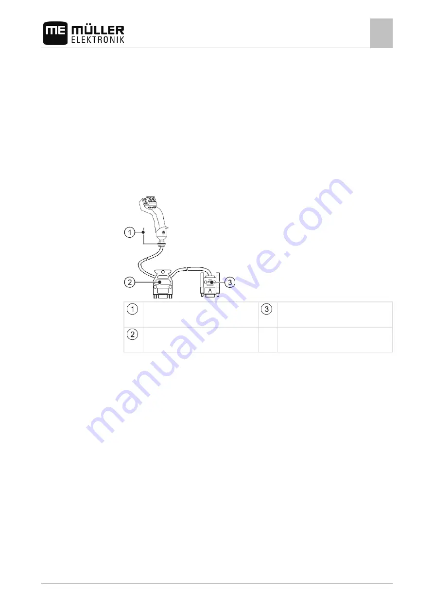
Fitting a joystick with a D-Sub connector
Mounting angle
For attachment in the cabin
Connector for connection to the
terminal
Socket for connection to the basic
vehicle harness
You fit the joystick as follows:
1. Fit the joystick next to the driver on the right.
2. Plug the connector of the basic vehicle harness into the joystick socket.
3. Connect connector A of the joystick to the CAN bus socket of the terminal. For
the majority of terminals from Müller-Elektronik this is going to be the A socket.
⇨
The joystick now connects the basic vehicle harness with the terminal.
⇨
When the terminal is switched on, the LED on the joystick lights up.
2
2.1
Procedure


