3.10
Operating Parameter Chart
1
See Section 3.7 to 3.9.
2
Factory set. Does not apply when “iF” is 0.
NOTE:
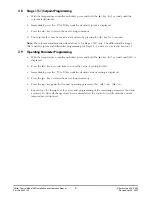
While programming the temperature controller make sure that the enter key is pressed to
enter the desired value. After 10 seconds of inactivity, the display will return to its normal function.
Any setting changes will take effect immediately after the enter key is pressed.
3.11
Temperature Control Calibration Accuracy
Once the installation wiring is completed for the chiller control box, check the calibration accuracy of
the temperature control as outlined below:
a. Allow the product temperature to stabilize for a minimum of 15 minutes.
b. Using an accurate electronic thermometer, determine the actual temperature of the solution.
c. If the known product temperature does not correspond with the temperature display, the
temperature control will require an operating parameter correction. This procedure is described in
Sections 3.8 and 3.9, and is adjusted using the “So” code.
Chiller Control Model 200 Installation and Operation Manual
9
Effective June 22, 2000
Part No. 9843143
Revised April 8, 2002
Recommended
Range
4d Direct Cooling
Code
Settings
Adjustment
Parameter Description
S1
34
1
34 to 55
Setpoint Stage 1
H1
1
1
1 to 9
Differential stage 1
S2
2
1
1 to 40
Setpoint stage 2 (differential to stage 1)
H2
1
1
1 to 9
Differential stage 2
S3
3
1
1 to 40
Setpoint stage 3 (differential to stage 1)
H3
1
1
1 to 9
Differential stage 3
S4
4
1
1 to 40
Setpoint stage 4 (differential to stage 1)
H4
1
1
1 to 9
Differential stage 4
LL
15
-45 to HL
Lower setpoint limit
HL
55
LL to 99
High setpoint limit
Cc
2
0 to 9 minutes
Anti-short cycling
CH
0
N/A
N/A
rt
0
0 to 99 min/unit
Soft start
AH
40
0 to 50
High alarm related to setpoint
AL
-5
-50 to 0
Low alarm related to setpoint
Ad
1
1 to 9
Alarm differential
At
30
0 to 99 minutes
Alarm time delay
So
0
-/+ 20
Sensor offset (used to calibrate sensor if needed)
Un
1
0 = C & 1 = F
Temperature units of measure (Celsius or Fahrenheit)
Pu
1
1 to 99 seconds
Display updating time delay
iF
0
N/A
Binary input (0-not used)
Sb
10
2
1-20
Binary set back (not used)
1d
0
N/A
N/A
iS
5
3-90 seconds
Interstage time delay (see Figure 2)
Summary of Contents for Hydro-Guard 200 Series
Page 14: ......


