3.4
Status-LEDs
Function of LEDs at the front side:LED
Power
shows that the device is powered on.
LED
Active
shows that lasershow output is running (shutter signal = On).
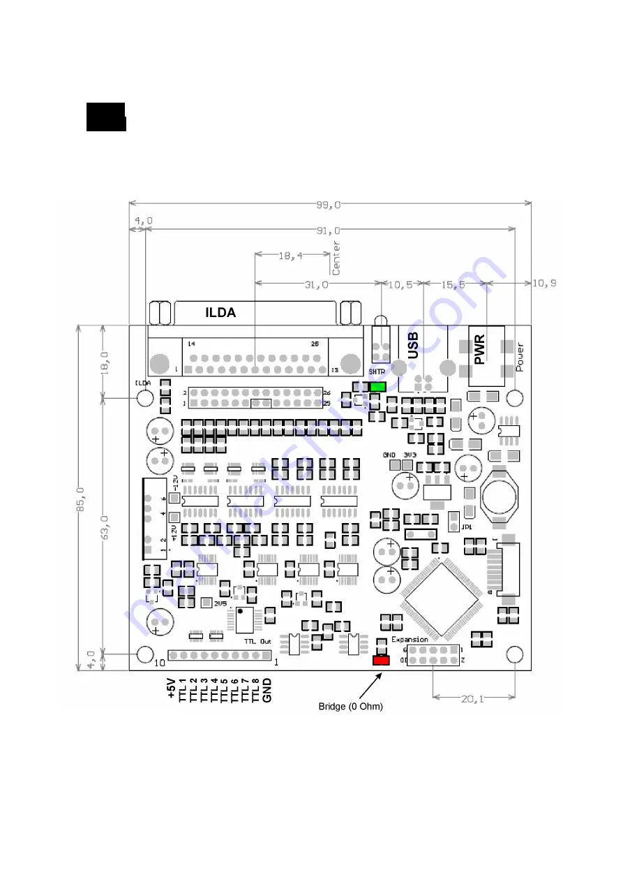
3.5
Boardlayout and Dimensions (Fig.2)
All dimensions in millimeters
12
Page 1: ...ness completeness or quality of the information provided Liability claims regarding damage caused by the use of any information provided including any kind of information which is inclomplete or incor...
Page 2: ...new DLL with older software Page 8 3 Signal connectors Page 9 3 1 Connecting Scanner and Colorsignals 3 2 TTL Outputs Page 11 3 3 DMX Signals 3 4 Status LEDs Page 12 3 5 Boardlayout and dimensions 4...
Page 3: ...nnector X Y outputs symmetrical Colour outputs single ended Error tolerant dataprotocol Plug n play driver for all Windows operating systems from XP 64Bit also User API for driver DLL compatible with...
Page 4: ...onditions unless it is verifiable that damage existed when the product left factory Also any liability claims regarding damage caused by the use of this product will be rejected 2 2 Step by step drive...
Page 5: ...are asked to search the Internet for drivers select no if you install your first EasyLase USB II do not use the automatic installation option and then continue If you have already installed an EasyLas...
Page 6: ...Now choose the drive and directory where the driver files are located If you want to install from the CD choose Confirm with Windows will search the driver and install it 6...
Page 7: ...ld be listed in the hardware manager as USB Laser Device By clicking the right mouse button to the entry EasyLase II and then click on properties the device information will be displayed Here you can...
Page 8: ...he old file Easylase dll with this file Your software now will support the old EasyLase hardware as well as the new EasyLase II and also all other devices listed above Note If your software does not w...
Page 9: ...d only maximum deflection angle of the scanner or laser projector will be the half value only Same happens if one of the signals will be connected to GND Always connect the GND pin Pin 25 of the DSUB...
Page 10: ...M against GND Signals Intensity and Colour Cyan are connected on board The software must decide if 5 colours plus an intensity channel or 6 colours are used Note When using 5 colours intensity the 6th...
Page 11: ...pin DSUB of the boxed device 3 3 DMX Signals The DMX signals are located at a 10pin expansion connector The line drivers for DMX are already located on board Normally the signals In In Out and Out wi...
Page 12: ...unction of LEDs at the front side LED Power shows that the device is powered on LED Active shows that lasershow output is running shutter signal On 3 5 Boardlayout and Dimensions Fig 2 All dimensions...
Page 13: ...functions work check if the DLL Jmlaser dll or the driver Jmlaser mld for Mamba is located in the right directory of the software Check if the output of the software is enabled and if the right outpu...