


8.2 Valve Drive
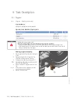
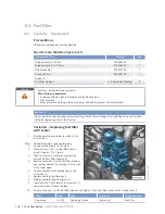
8.2.1 Valve clearance – Check and adjustment
Preconditions
☑
Engine is stopped and starting disabled.
☑
Engine coolant temperature is max. 40° C.
☑
Valves are closed.
Special tools, Material, Spare parts
Designation / Use
Part No.
Qty.
Feeler gage
Y20010128
1
Torque wrench, 20–100 Nm
F30026582
1
Box wrench, 14 mm
F30028346
1
Allen keys, 2-10 mm
F30453050
1
Barring tool
F6790714
1
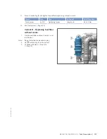
Preparatory steps
1.
Remove cylinder head cover (→ Page 101).
2.
Install barring tool on crankshaft (→ Page 96).
3.
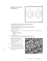
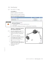
Rotate crankshaft with barring tool in engine direction of rotation until “OT-A1” (TDC-A1) mark and pointer
are aligned.
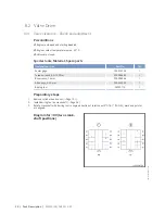
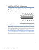
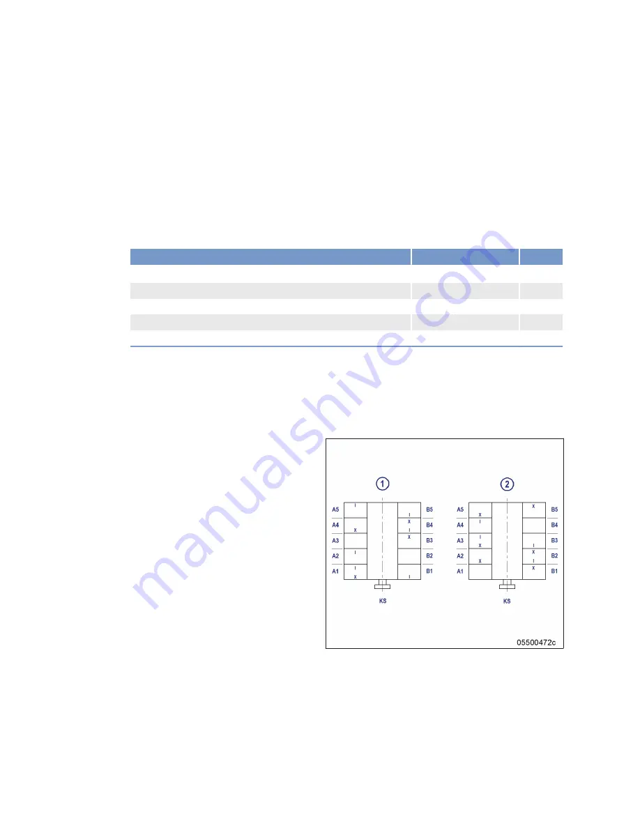
Diagram for 10V (two crank-
shaft positions)
98 | Task Description | MS150100/04E 2015-09
TIM-ID: 0000054769 - 003


