background image

MTM – Spindler & Schmid GmbH ∙ Amtsgericht Ulm, HRB 2321 ∙ Geschäftsführer: René Spindler ∙ W

Telefon (0 73 89) 6 00 ∙ Telefax (0 73 89) 3 90 ∙ [email protected] ∙ www

    in 

    Germany

Read instruction manual attentively before useing your device!

9

Starting up of device:

1. 

Connect air connection (1) and air hose of the compressor. Lock the snap ring of  the Mody coupling  

 (clutch).

2. 

Connect insert tool (7) and seat (6): Retract the clamping collar (4), insert the mounting    


mandrel (5) of the tool (7), then loose the clamping collar (4) to fix the tool (7).

3. 

Pull the trigger (2) to start the impact mechanism (3).

4. 

Release the trigger (2) to stop the impact mechanism (3).

5. 

To change the tool, retracte the clamping collar (4) and remove the tool (7), than follow step 2..

Only use certified air hoses (up to 20 bar) with certified couplings and do not work with a higher pressur than 7 

bar!

Always check the tight fitting of all couplings, to reduce the danger of disconnection and randomly moving of 

air hoses!

Only use original MTM-Spindler & Schmid GmbH certified tools!

Use of non-certified tools invalids all warranty claims!

Only use tested and certified compressors!

Due to safty reasons, the devices are not equipped with a non-stop function!

Before using your device check all screws and fittings for tight connection. Lose parts must be glued in with 

specific glue. Make sure to lubricate moving parts, we recommend lubrication adequate for waters protection.

Attention: 


before replacing tools, always separate impact mechanism and air connection,


to eliminate the risk of injury by pressing the trigger (2) unintended. 


Tool replacement only by statical impact mechanism. 


Remove the mounting mandrel (5) of your insert tool by pulling at the insert tool in  


one direction and pulling back the campling collar (4) in the other direction.


Insert the new tool (7) by putting the mounding mandrel (5) into the hexagon shape  


of the tool‘s seat (6).

hexagon end for clamping collar (4) of insert tool 

seat (6)

conus connection for insert tool‘s shaft (8)

mounting mandrel 

closed

mounting mandrel 

open

Attention: 


Device is not design for strong 

leverages!

Leveraging only when mounting mandrel (5) 

connection is closed. 

Strong leverage may break the mounting 

mandrel!  


Summary of Contents for Powerhammer

Page 1: ...e in Germany Änderungen vorbehalten Turbo Digger Druckluftspaten TurboSpaten TurboHammer Powerspaten Powerhammer MTM Originalbetriebsanleitung instruction manual Deutsch English TD 80 TD 60 TD BS TD D TD C ...

Page 2: ......

Page 3: ...e der EG Maschinenrichtlinie 2006 42 EG und in Übereinstimmung mit der EG Richtlinie 2000 14 EG hergestellt wurde Verantwortliche Person René Spindler Weberstr 53 D 72535 Heroldstatt Die benannte Stelle wurde eingeschaltet zur Prüfung der Arbetissicherheit gemäß GPSG Die Maschinen hat das Werk im Originalzustand geprüft und voll funktionsfähig verlassen Bei einer Veränderung der Maschine die nicht...

Page 4: ...bare Fehlanwendungen Betrieb der Geräte ohne entsprechende persönliche Schutzausrüstung Betrieb der Geräte entgegen der in der Betriebsanleitung vermerkten bestimmungsgemäßen Verwendung Betrieb der Geräte ohne festen Stand nicht gesicherte Leiter Bediener steht in der Baggerschaufel etc Betrieb der Geräte mit falsch eingestelltem Kompressor Festsetzen des Auslösemechanismus der Maschinen durch Kle...

Page 5: ...on Read instruction manual Wear safety shoes Foreseeable misuse Use of the devices without personal protection gear Use of the devices against the purposes mentioned in this manual instruction Use of the devices without safe stand no safe letter operater standin in an excavaters shovel etc Use of the devices with rong calibrated compressor Fixation of the trigger mechanism with tape Unsufficient l...

Page 6: ...en 2 Nicht gegen Mensch Tier und Energiequellen Gas Wasser Stromleitung richten Achtung Das Gerät darf aufgrund seines Aufbaus und der Wechsel werkzeuge nicht in explosionsgefährdeten Räumen benutzt werden 3 Boden auch Erdreich Wand Decke auf Kabel und Leitungen prüfen 4 Vermeiden Sie eine ungünstige Körperhaltung Sorgen Sie jederzeit für einen sicheren Stand um auf normale oder unerwartete Bewegu...

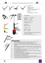
Page 7: ...he TD shall not be used in explosive endangered rooms 3 Before starting up the TD check the ground for ducts lines and cables to avoid damage 4 A safe standing in a good position is important to react on unexpected movements of the TD Unexpected movements or even a tool break can cause damages to the lower extremities 5 Only operate with approved and certified air pressure hoses up to 20 bar with ...

Page 8: ...nnhülse 4 und Einführen des Aufnamedorns 5 in die Werkzeugaufnahme 6 Spannhülse 4 loslassen damit das Werkzeug 7 festen Sitz hat anschließend auf festen Sitz prüfen Luftanschluss durch Ineinanderstecken der Schnellverschlusskupplung 1 gegebenenfalls Siche rungsring bei Gebrauch einer Mody Kupplung festdrehen Einschalten des Schlagwerkes 3 durch Drücken des Auslösegriffs 2 Schlagwerk 3 nur betätige...

Page 9: ...claims Only use tested and certified compressors Due to safty reasons the devices are not equipped with a non stop function Before using your device check all screws and fittings for tight connection Lose parts must be glued in with specific glue Make sure to lubricate moving parts we recommend lubrication adequate for waters protection Attention before replacing tools always separate impact mecha...

Page 10: ...tzieren Sie das Spatenblatt 7 leicht schräg auf dem Erdreich bzw des zu schneidenden Holzes Betätigen Sie den Auslösebügel 2 Unter leichtem Gegendruck dringt das Werkzeug 7 gleichmäßig in das Erdreich ein und durchschneidet dabei das Wurzelwerk Bei größeren Wurzeldurchmessern geben Sie dem Spaten 7 die Zeit die Wurzel zu durchtrennen indem Sie während des Schlagwerkbetriebes 3 den Gegendruck halte...

Page 11: ...only sharp tools insert spade plant bale spade Place the tool on the surface of the soil Start the impact mechanism by using the trigger 2 Press the insert spade or plant bale spade continiously forward Never try to pull the insert tool out of the ground before roots are cut Move the tool sideways up to the time you feel that the roots have been cut Than push the handle forward away from yourself ...

Page 12: ...gs ursprung Gefährdungs ort Beschreibung der Gefährdung Schutzmaßnahme Restrisiko PLr1 Risiko index1 1 S1 minderschwere Verletzungen S2 schwere Verletzungen F1 seltene Häufigkeit F2 höhere Häufigkeit a geringes Risiko b mäßiges Risiko Erfassen Druckluft schlauch Schlauchver bindung Objektteile der Arbeitsfläche Verbindung zwischen Spaten und Kompressor Verbindung zwischen Spaten und Druckluft schl...

Page 13: ...rd Counter measures Remaining risk PLr1 Risk index1 1 S1 minor injuries S2 major injuries F1 low frequency F2 high frequency a low risk b middle risk Hitting Air hose Air connection Parts of altered objects connection between compressor and spade connection between air hose and spade Wall or ceeling covered with objects risk of injury due to bursting air hoses risk of injury due to bursting air co...

Page 14: ...nmittel baren Umfeld der laufenden Maschine Materialien oder Arbeitsgerät fällt herab Finger werden an der Werk zeugaufnahme eingeklemmt Pneumatisch betriebene Spaten sondern bei Betrieb einen Lärmpegel bis 99 5 dB in unmittelbarer Nähe 1m ab dadurch Gefahr des Verlusts oder dauerhafter Beeinträchtigung des Hörvermögens S2 F1 S1 F1 S2 F2 a a b Nichtbeachtung der Hin weise Unachtsamkeit Unachtsamke...

Page 15: ...ation Work on wall and celing connection between insert tool and device close range area around the working device spade falls down objects fall down fingers get squeezed when moun ting mandrel is touched Pneumatic spades emmit a noise level about 99 5 dB in close range 1m it causes a danger to affect hearing ability S2 F1 S1 F1 S2 F2 a a b Not paying attention to safety instruction carelessness c...

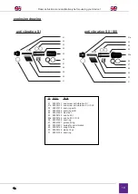
Page 16: ...6b Zylinder S III 17 Feder 18 Sicherungsring 19 Spannhülse 20 Stiel Sprengbild Aluminium Griff TD 80 Schlagwerk Lanzengriff TD 60 T Griff TD BS Pistolengriff TD C D Griff TD D Stiel 1 Gummigriff 2 Griffrohr 2a AL Griff 3 Verschlussstopfen 4 Ventilfeder 5 Ventil 6 MS Patronenkörper 6a AL Patronenkörper 7 Kupplungsstecker 8 Auslösebügel 8a PA Auslösebügel 9 Sicherungsstift 99001107 99002055 99002067...

Page 17: ... screw S II III 13 piston 13a piston S II 13b piston S III 14 O ring 15 ball SI II 15a ball S III 16 cylinder S I 16a cylinder S II 16b cylinder S III 17 tension spring 18 security ring 19 collar clamp 20 shaft explosion drawing Aluminium Griff TD 80 Impact mechanism Lanzengriff TD 60 T Griff TD BS Pistolengriff TD C D Griff TD D Stiel 99002066 99002090 99002056 99002057 99002058 99002059 99002060...

Page 18: ... 21a Dämpferendverschraubung S II S III 22 Dichtring Satz A 23 Dichtring Satz B 24 Stahlläufer 25 Endhülse für Dämper S I 25a Endhülse für Dämpfer S II SIII 26 Dichtring 27 Nutring 28 Dämpferfeder 29 Dämpferstützrohr 30 Stifte Satz 8 Stk 31 Dichtungsring 99002141 99002142 99001015 99001034 99001203 99002145 99002146 99001035 99001001 99001207 99002143 99000129 99001034 Nr Name Art Nr 21 25 23 27 2...

Page 19: ... S I 21a end screw anti vibration S II S III 22 seal ring set A 23 seal ring set B 24 steel bar 25 end hull S I 25a end hull S II SIII 26 seal ring 27 grooved ring 28 spring for anti vibration 29 support tube 30 pin set 8 pc 31 seal ring 99002141 99002142 99001015 99001034 99001203 99002145 99002146 99001035 99001001 99001207 99002143 99000129 99001034 Nr Name Art Nr 21 25 23 27 22 26 24 28 29 30 ...

Page 20: ...rsetzung vorbehalten Jedwede Art der Reproduktion einschleißlich Fotokopie Mikrofilm elekt ronischer Datenerfassung etc bedürfen der expliziten schriftlichen Genehmigung durch den Herausge ber Der Nachdruck auch Auszugsweise ist ohne explizite schriftliche Genehmigung verboten Die Betriebsanleitung entspricht dem technischen Stand bei Drucklegung Änderungen vorbehalten EN This manual is published ...

Reviews: