CONGRATULATIONS! YOU HAVE JUST PURCHASED THE BEST SURGE PRO-
TECTION IN THE INDUSTRY!
Adhering to these instructions guarantees maximum performance of this Protection device.
1. INTRODUCTION
The MAxx/D protects electronic equipment from surges and Radio Frequency Interference (RFI)
on the mains power supply. The MAxx/D has a unique 3 stage combination of protection elements
providing fi ltering, surge protection and ring suppression.
2. IMPORTANT SAFETY INFORMATION
WARNING
To avoid risk of shock or fi re which can be caused by incorrect wiring or
regulation, whenever installing mains/power surge protection devices the following
safety procedures should be followed :-
Always isolate supply before installing or removing any covers.
The maximum rating of fuse/circuit breakers must not exceed the lower of:
a) The maximum value specifi ed for the surge protection device
b) The power supply short circuit current
c) The maximum rating of equipment protected by the surge protection device
Examples:
For an in-line surge protection device with maximum specifi ed through or line
current of 10A :-
a) Connected to a 30A power supply - Protect with 10A maximum.
b) Connected to a 8.5A UPS or standby generator - Protect at 5A (8.5/1.7A, 1.7 is
the usual safety margin of fuses).
c) Connected to equipment rated at 5A maximum - Protect at 5A maximum.
Correct polarity of live, neutral and earth (L, N, E) is essential. Check both at SPD
and source of supply.
The supply voltage must be less then the maximum working voltage of the SPD. In
systems where neutral is bonded to earth, this is achieved for a correctly selected SPD
under normal operation. Pay particular attention to UPS and standby generator
regulation and neutral earth bond.
Note: Ensure that surge protection devices are removed before performing
insulation
or
fl ash tests on equipment.
3. INSTALLATION
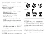
The MAxx/D units simply clips on to “G” (EN 0035 DIN46277-1) or “Top Hat”/T-section (EN
50022, DIN46277-2) DIN rail.
3.1 CONSTRUCTION
The casing of the MAxx/D has screw-clamp terminals for input and output connections. The
maximum allowable wire cross section for the terminals is 2.5mm
2
(12 AWG).
www.telematic.com
www.telematic.com
www.telematic.com
www.telematic.com
www.telematic.com
www.telematic.com
www.telem
atic.com
www.telem
atic.com
www.telem
atic.com
www.telem
atic.com
www.telematic.com
www.telematic.com
For "G" rails :-
For "Top Hat" rails :-
Clip on like this
Clip off like this
Not like this
Clip on like this
Clip off like this
Not like this
Figure 1
Installation
3.2 CONNECTION
Connect the incoming mains to the “LINE” side of the MAxx/D device, as indicated on the
product labelling. The protected equipment is connected to the “LOAD” side. The Live wire
must be connected to the “L” terminal of the MAxx/D. If two core cable without an integral
earth wire is being used, for full protection, the earth “E” terminal should be bonded to a suit-
able system earth point.
NOTE:
An internal thermal fuse is provided but a fuse or circuit breaker should be inserted
in the mains input side of the incoming supply. Rating will be according to the required load
current
4.0 MAINTENANCE
The lifetime of the MAxx/D is dependent on the number of surges experienced, however, the
unit will typically provide maintenance-free protection over a twenty year period. In the event
of a surge exceeding the device ratings, the unit is designed to fail-safe, due to the secondary
protection elements going short circuit, the equipment therefore remains protected.
NOTE:
The MAxx/D is designed to limit the voltage that can occur both line-line and line-
earth. Any system insulation test should be carried out with the MAxx/D disconnected from
the circuit.


