MTI Freedom Axis Product Manual Download Page 5

FREEDOM UNIVERSAL 2.0

5

FREEDOM AXIS

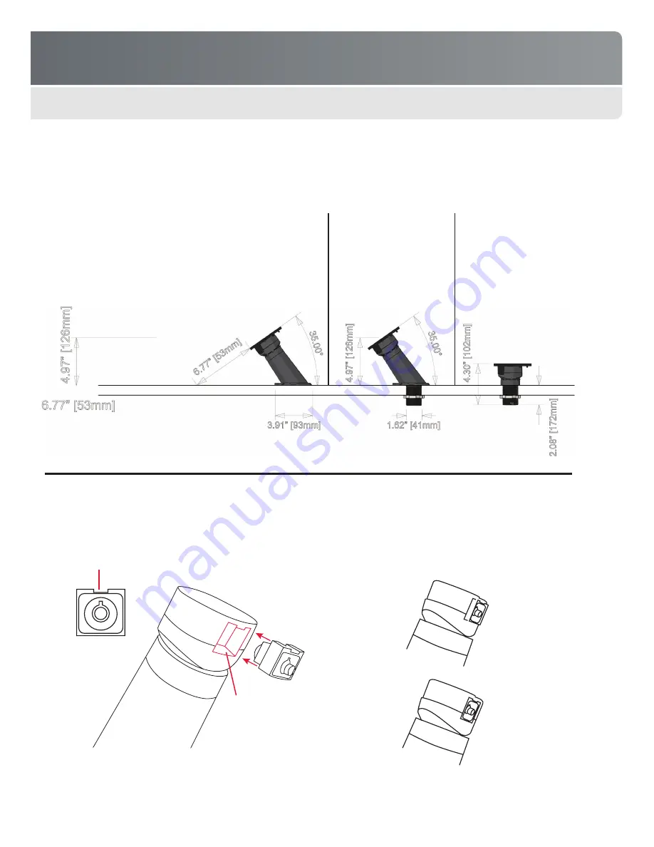
Base Options & Dimensions

Freedom Axis offers three base options – a surface-mount riser, a through-hole riser, and through-hole mount. Both risers present the 
mounted device at a 35-degree angle.

Installing the Lock

The diagram below shows how to install a new lock unit.

INSTALLATION & SETUP

Surface-mount riser


Attaches directly to fixture 

top using mounting screws 
or VHB adhesive pad

Through-hole riser


Installs through fixture 

top (requires 1.65” hole)

Through-hole mount


Installs through fixture 

top (requires 1.65” 
hole). Recommended 
for angled fixtures 

(35-degree minimum and 
above) or vertical wall 

installations.

1�

 Orient new lock so detent is facing up

Incorrect (not flush)

Correct (flush)

2�

 Insert lock into the socket until lock 

snaps in place; edge of lock should 
be flush with surface of puck

Summary of Contents for Freedom Axis

Page 1: ...2008 MTI All Rights Reserved FREEDOM AXIS MTI P N 063 1155 00 Rev B Release Date January 2013 PRODUCT MANUAL...

Page 2: ...e Options Dimensions 5 Installation Setup 5 Installing the Lock 5 Installing System Components 6 Mounting Products 8 Removing Device from Saddle 9 Removing Base from Fixture 10 Operation 11 Basic Oper...

Page 3: ...once again lock it in place System Components Features Power supply not shown Provides power to recharge mounted device Mounting saddle Secures device to puck SmartCable not shown Delivers correct pow...

Page 4: ...le connection Cable security tab Mounting bracket slot VHB adhesive pad Secures device to saddle Mounting bracket optional Two brackets fit around device to provide additional mechanical security see...

Page 5: ...ION SETUP Surface mount riser Attaches directly to fixture top using mounting screws or VHB adhesive pad Through hole riser Installs through fixture top requires 1 65 hole Through hole mount Installs...

Page 6: ...d make sure the SmartCable will not interfere with fixture wall or other positions and will rotate without interference Installing System Components Before you begin Review mounting recommendations an...

Page 7: ...he bottom of the base cable remains on top of mounting surface or down through a hole in the fixture top cable hidden below mounting surface 3 Using the four mounting holes as a guide pre drill pilot...

Page 8: ...outing before attaching the saddle If a locating device is included in your kit use this device to place the saddle in the correct location Plug loose end of SmartCable into the power input jack on th...

Page 9: ...the saddle The plate only fits on one way be sure it is flat against the back of the tablet Rotate tool handles 90 degrees to free the saddle You may need to rotate back and forth several times to lo...

Page 10: ...t the power supply cable from the base 2 Insert removal tools into notches on both sides of the base 3 Turn each tool handle 90 degrees to free the base 4 Remove the base The adhesive pad should split...

Page 11: ...s demo experience or to perform product updates e g upgrade the device s firmware or apps Lift saddle device assembly from puck Place saddle device assembly onto the puck see note at left Saddle Secur...

Page 12: ...vice pursuant to part 15 of the FCC Rules These limits are designed to provide reasonable protection against harmful interference when the equipment is operated in a commercial environment This equipm...

Page 13: ...SmartCables FlexSensors Membrane Sensors anti skid pads anti rotation brackets VHB adhesive pads X and L brackets CC and DC brackets cable clamps zip ties and installation retrieval and removal tools...

Reviews: