13
S
ection
4 — A
SSembly
& i
nStAllAtion
Note:
For the chute elbow to be properly installed, the bottom
edge must fall
over
the bottom of the deck opening and the tab
on top of the elbow should rest
above
the deck opening.
IMPORTANT:
If the retainer clip is not present on the mowing deck, on
some units, one has been included with hardware pack 689-00329.
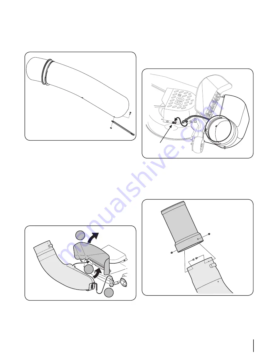
Attach the retainer hook (96606) with a self-tapping screw factory
installed in the deck in the position noted in Figure 4-21. Remove the
screw in the deck and reinstall with the retainer hook.
Retainer Clip
Figure 4-21
7.
Install the chute adapter onto the chute elbow by lining
up the tabs and sliding the adapter over the chute elbow,
as in Figure 4-22. Secure the chute adapter by installing
two (2) 710-3013 hex bolts and two (2) 712-0442 cap lock
nuts, included in hardware pack 689- 00329, into the holes
provided. See Figure 4-22.
Figure 4-22
2.
Attach the rubber strap (723-04009A), from hardware pack
689-00329, to the upper chute tube using the machine
screw (710-0924) from the same hardware pack. Secure
with a flange lock nut (912-3027) supplied in the same
hardware pack. See Figure 4-19.
Figure 4-19
Installing the Discharge Chute
1.
Reinstall cutting deck onto the tractor reversing the instructions
for Deck Removal in operator’s manual of the tractor.
2.
Raise the deck to its highest position.
3.
Raise the chute deflector (A in Figure 4-20) on the deck
and hold it while you position the discharge chute over the
chute opening.
4.
Insert the hinge pin of the discharge chute into the tube on
the chute stop bracket. See B in Figure 4-20.
5.
Rotate the chute around the deck so that its front edge fits
snugly into the deck opening. Lower the chute deflector
slowly (C in Figure 4-20).
A
C
B
Figure 4-20
6.
Attach the retainer strap on the discharge chute to the
retainer clip on the deck. Refer to Figure 4-21.


