


10
11
Rev. 24.07.2018
Rev. 24.07.2018
A
B
C
D
E
F
G
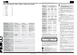
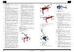
A.
Upper cutter arm handle
B.
Upper cutter arm
C.
Return spring
D. Support
E.
Lower cutter
F. Limiter
A
E
F
B
C
D
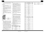
MSW-HS8
A.
Lever handle
B.
Return spring
C.
Upper cutter
D.
Lower cutter
E.
Mounting holes
F.
Clamping disc
G.
Hole for round bar cutting
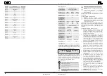
MSW-MPS
A.
Guide wheel
B. Pawl
C.
Lever handle
D.
Cutting wheel
•
Ensure the free space of 1 m around the device to
avoid damages.
•
The operator should have enough space to operate
the device.
•
At least 2 persons should take the device out of its
packaging and prepare it for assembly (this does not
apply to the model MSW-MPS)
Installing the appliance:
•
Model MSW-MPS does not require assembly.
•
Model MSW-HS8
Install the lever with the handle (A) in the upper part
of the device. Secure the connection with screws.
•
Models MSW-MSB500, MSW-MSB800, MSW-
MSB1000:
Install the supports (D) in the lower part of the device,
at the front and the rear. Secure the connection with
screws.
3.3. DEVICE USE
Before working, it is recommended to mark the shearing line
on the workpiece.
Models MSW-MSB500, MSW-MSB800, MSW-MSB1000.
Workpiece cutting:
a)
Raise the device arm while holding the handle with
one hand.
b) While holding the workpiece, place it level and
perpendicular to the cutters.
c)
Insert the workpiece between the device cutters.
d)
Carry out cutting with one hand by pressing the device
arm held by its handle while grasping the workpiece
with the other hand. The workpiece will be cut.
CAUTION! Do not bring your hand closer than 20 cm
to the device cutters when holding the workpiece.
e)
Raise the device arm.
f)
Remove the workpiece.
g) Put aside the cut part of the workpiece and the
workpiece itself at the appropriate place. Keep order
at the workplace.
CAUTION! Exercise care when grasping the
workpiece before and after working. The workpiece
can have sharp edges.
CAUTION! During cutting with the device, workpiece
recoil can occur. Exercise care and use the safety
gloves and goggles.
Model MSW-HS8
a) While holding the workpiece, place it level and
perpendicular to the cutters.
b)
Insert the workpiece between the device cutters.
c) Press the workpiece by means of clamping disc.
Rotate the clamping disc to change its position. This
activity is not required when cutting round bars.
d)
Press the device lever.
CAUTION! Do not bring your hand closer than 20 cm
to the device cutters when holding the workpiece.
e)
Raise the device lever.
f)
Release the disc pressure onto the workpiece. This
activity is not required when cutting round bars.
g)
Remove the workpiece.
h) Put aside the cut part of the workpiece and the
workpiece itself at the appropriate place. Keep order
at the workplace.
Model MSW-MPS
3.2. PREPARING FOR USE
Appliance location:
The device shall always be used on thean even, stable, clean
and dry surface and out of reach of children and persons of
unsound mind.
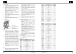
MSW-HS1000
A
B
C
D
Number
of part
Description
Number of
pieces
1
Lower blade
1
2
Clevis pin
4
3
Body
1
4
Connecting plate
1
5
Shaft
1
6
Washer
4
7
Nut
4
8
Leg
2
9
Mandrel
1
10
Washer
2
11
Nut
4
12
Bolt
4
13
Mandrel
2
14
Cover
1
15
Bolt
4
16
Upper arm
1
17
Bolt
4
18
Upper blade
1
19
Bolt
2
20
Handle roller
1
21
Holder
1
22
Spring
1
List of elements
MSW-MSB500, MSW-MSB800, MSW-MSB1000
1.
Guide wheel
2.
Upper set screw
3.
Cutting wheel
4.
Lower set screw
5.
Lower shaft
Adjustment
a)
The cutting wheel edge should tie in with the guide
wheel edge in depth near to the workpiece thickness.
It is recommended to try and set the wheels coverage
depth using an unnecessary piece of material of the
same type as the material to be worked.
b)
To set the wheels in relation to each other, firstly
loosen the upper and lower set screws.
c)
To increase wheel coverage, tighten up the lower
clamping screw (clockwise) until the desired wheel
coverage is reached. Then, tighten the upper set
screw until it offers light resistance. To reduce wheel
coverage, loosen the lower clamping screw and turn
the upper set screw clockwise until the desired wheel
coverage is reached. Then, tighten the lower set
screw until it offers light resistance.
d)
If the cutting wheel does not rotate freely enough,
turn the lower roller and readjust the ser screws.
Cutting
a) While holding the workpiece, place it level and
perpendicular to the cutters.
b)
Insert the workpiece between the cutting wheel and
the guide wheel. Make sure that the superfluous
workpiece side is the on the right-hand side of the
device (on the side of the guide wheel).
c)
Make sure that the pawl is above the ratchet drill
and pull the handle forward while pressing it lightly
towards cutting with other hand.
CAUTION! Do not bring your hand closer than 20 cm
to the device cutters when holding the workpiece.
d)
If it is necessary to cut the workpiece further, turn
the lever opposite to the cutting direction and then
turn it again towards cutting. The next section of
the element will be cut together with rotation of the
wheels. Repeat this activity until the desired effect is
obtained.
e)
Remove the workpiece.
f)
Put aside the cut part of the workpiece and the
workpiece itself at the appropriate place. Keep order
at the workplace.
3.4. CLEANING AND MAINTENANCE
•
Any blockages and jammed residues after the
workpiece must be removed using suitable tools (e.g.
by means of a hook or piece of wood).
•
After each work, remove any dust, leavings of the
workpieces and impurities from the device.
•
Use cleaners without corrosive substances to clean
each surface.
•
After cleaning the device, all parts should be dried
before reusing it.
•
Store the unit in a dry, cool place, free from moisture
and direct exposure to sunlight.
•
Regular inspections of the device must be carried out
in terms of its technical efficiency and any damages.
•
Regularly grease the movable elements depending on
the frequency of their use.
•
During lubrication, pay attention not to grease the
external surface of the guide wheel (this applies to the
model MSW-MPS).
ATTENTION!
This product’s exploded view
can be found on the last pages of the operating
instructions (pp. 38-39).
ASSEMBLY DRAWINGS
1
2
3
4
5
Number
of part
Description
Number of
pieces
1
Shaft
1
2
Spring
1
3
Clevis pin
1
MSW-HS8


