M S-7356 M ainboard
C-12
The
InstallShield Wizard
will begin automatically for installation showed as following:
Click on the
Next
button to proceed the installation in the welcoming window.
7356v1.0-C_ICH9R RAID.p65
2007/5/22,
下午
05:30
12
Page 1: ...i P35 Diamond series MS 7356 v1 X Mainboard G52 73561X1...
Page 2: ...uron are registered trade marks of AMD Corporation Intel and Pentium are registered trademarks of Intel Corporation PS 2 and OS 2 are registered trademarks of International Business Machines Corporati...
Page 3: ...ace the power cord such a way that people can not step on it Do not place anything over the power cord 8 Always Unplug the Power Cord before inserting any add on card or module 9 All cautions and warn...
Page 4: ...interference by one or more of the measures listed below Reorient or relocate the receiving antenna Increase the separation between the equipment and receiver Connect the equipment into an outlet on...
Page 5: ...v WEEE Waste Electrical and Electronic Equipment Statement...
Page 6: ...vi...
Page 7: ...vii...
Page 8: ...Processing Unit 2 2 Memory 2 7 Power Supply 2 11 Back Panel 2 12 Connectors 2 14 Jumper 2 21 Button 2 22 Slots 2 23 LED Status Indicators 2 25 Chapter 3 BIOS Setup 3 1 Entering Setup 3 2 The Main Men...
Page 9: ...B 3 DOT Dynamic OverClocking B 5 Clock B 6 Voltage B 7 FAN Speed B 8 Temperature B 9 User Profile B 10 Appendix C Intel ICH9R SATA RAID C 1 ICH9R Introduction C 2 BIOS Configuration C 3 Installing Dr...
Page 10: ...X ATX mainboard The P35 Diamond Series mainboards are based on Intel P35 ICH9R chipsets for optimal system efficiency Designed to fit the ad vanced Intel Core 2 Quad Core 2 Duo Pentium Celeron LGA775...
Page 11: ...please visit http global msi com tw index php func testreport LAN Supports PCIE LAN 10 100 1000 Fast Ethernet by Realtek 8111B Audio Chip integrated by Realtek ALC888T Flexible 8 channel audio with ja...
Page 12: ...1 Optical S PDIF Out On Board Pinheaders Connectors 3 USB 2 0 pinheaders 1 1394 pinheader 1 chasis intrusion connector 1 SPDIF out pinheader 1 CD in connector 2 H W OC pinheaders optional 1 front audi...
Page 13: ...T JAUD1 CPUFAN1 JPW1 JPW2 SYSFAN1 SYSFAN4 SYSFAN3 J1394_1 JCOM1 FDD1 JCD_IN1 JSPDIF2 JUSB3 JUSB2 JUSB1 JFP2 JFP1 SATA7 SATA6 SATA5 SATA4 SATA3 IDE1 ATX1 Top mouse Bottom keyboard Top LAN jack Bottom U...
Page 14: ...ly and may vary from the packing contents of the product you purchased Power Cable User s Guide and Quick Guide MSI motherboard MSI Driver Utility CD Floppy Cable IDE Cable Back IO Shield 1394 Bracket...
Page 15: ...dures While doing the installation be careful in holding the components and follow the installation procedures For some components if you install in the wrong orientation the components will not work...
Page 16: ...2 14 SATA3 7 p 2 15 JFP1 2 p 2 18 JUSB1 3 p 2 20 SYSFAN3 p 2 16 J1394_1 p 2 17 FDD1 p 2 14 JSPDIF2 p 2 17 JCD IN1 p 2 19 JAUD1 p 2 19 PCI p 2 23 JCOM1 p 2 20 PCI_E p 2 23 SYSFAN1 p 2 16 Back Panel p...
Page 17: ...stem Always make sure the cooling fan can work properly to protect the CPU from overheating Make sure that you apply an even layer of thermal paste or thermal tape between the CPU and the heatsink to...
Page 18: ...to protect the contact from damage Before you install the CPU always cover it to protect the socket pin 3 The pins of socket reveal CPU Cooler Installation When you are installing the CPU make sure t...
Page 19: ...me Be sure to grasp on the edge of the CPU base Note that the align ment keys are matched 8 Cover the load plate onto the package 7 Visually inspect if the CPU is seated well into the socket If not ta...
Page 20: ...orrect di rection marked on it to lock the hooks 9 Press down the load lever lightly onto the load plate and then se cure the lever with the hook under retention tab locking switch Important 1 Read th...
Page 21: ...enhance the system performance Please refer to the following illustrations for population rules under Dual Channel mode 1 DIMM1 DIMM2 DIMM3 DIMM4 2 DIMM1 DIMM2 DIMM3 DIMM4 3 DIMM1 DIMM2 DIMM3 DIMM4 Th...
Page 22: ...t will automatically close Important You can barely see the golden finger if the memory module is properly inserted in the DIMM slot Volt Notch Important DDR3 memory modules are not interchangeable wi...
Page 23: ...Hynix HY5TQ1G831ZN 2GB v v DDR3 1066 Memory Slot Model Size 1 2 3 4 EBJ11UD8BAFA AC E v v v v Elpida Elpida J5308BASE 1GB v v EBJ51UD8BAFA AC E v v v v Elpida Elpida J5308BASE 512MB v v M378B2873CZ0...
Page 24: ...R3 1333 Overclock Memory Slot Model Size 1 2 3 4 8HCBJU ED v v TwinMOS Elpida J5308BASE DG E 512MB v v IMSH1GU13A1F1C 13G v v Qimonda Qimonda IDSH51 Q3A1F1C 13G 1GB v v M378B2873CZ0 CG9 v v v v Samsun...
Page 25: ...he power cable to touch the heatpipe as well ATX 24 Pin Power Connector ATX1 This connector allows you to connect an ATX 24 pin power supply To connect the ATX 24 pin power supply make sure the plug o...
Page 26: ...r a PS 2 mouse keyboard 1394 Port The IEEE1394 port on the back panel provides connection to IEEE1394 devices Optical S PDIF Out This SPDIF Sony Philips Digital Interconnect Format connector is provid...
Page 27: ...external CD player tapeplayer or other audio devices Line Out Green Line Out is a connector for speakers or headphones Mic Pink Mic is a connector for microphones RS Out Black Rear Surround Out in 4...
Page 28: ...D1 IDE Connector IDE1 This connector supports IDE hard disk drives optical disk drives and other IDE devices IDE1 Important If you install two IDE devices on the same cable you must configure the driv...
Page 29: ...e SATA3 SATA4 SATA5 SATA6 Important Please do not fold the Serial ATA cable into 90 degree angle Otherwise data loss may occur during transmission SATA7 supported by Marvell 88SE6111 VoIP Card Connect...
Page 30: ...is Ground and should be connected to GND If the mainboard has a System Hardware Monitor chipset on board you must use a specially designed fan with speed sensor to take advantage of the CPU fan contr...
Page 31: ...IN SIGNAL PIN SIGNAL 1 TPA 2 TPA 3 Ground 4 Ground 5 TPB 6 TPB 7 Cablepower 8 Cablepower 9 Key no pin 10 Ground J1394_1 1 2 9 10 IEEE1394 Bracket Optional S PDIF Bracket Optional S PDIF Out Connector...
Page 32: ...h lowreferencepull down to GND 9 RSVD_DNU Reserved Donot use JFP1 Pin Definition Front Panel Connectors JFP1 JFP2 These connectors are for electrical connection to the front panel switches and LEDs Th...
Page 33: ...ighDefinitionAudiodongle is connected to the analog header PRESENCE 0 when a High Definition Audio dongle is connected 5 LINEout_R Analog Port Right channel 6 MIC_JD Jack detection return from front p...
Page 34: ...10 USBOC Pin Definition Important Note that the pins of VCC and GND must be connected correctly to avoid possible damage USB 2 0 Bracket Optional Serial Port Connector JCOM 1 This connector is a 1655...
Page 35: ...rclock the FSB to increase the processor frequency by changing the jumpers JB1 and JB2 Follow the instructions below to set the FSB Jumper Important 1 Make sure that you power off the system before ch...
Page 36: ...CMOS Button SW1 There is a CMOS RAM on board that has a power supply from external battery to keep the system configuration data With the CMOS RAM the system can automati cally boot OS every time it i...
Page 37: ...0 GB s transfer rate The PCI Express x 1 slot supports up to 250 MB s transfer rate Slots PCI Express x16 Slot PCIE_2 Important The PCIE_2 and the PCIE_3 slots share 4 PCIE channels with the PCIE_4 s...
Page 38: ...Slot 1 INTA INT B INTC INTD PCI Slot 2 INT B INTC INTD INTA 32 bit PCI Slot Important When adding or removing expansion cards make sure that you unplug the power supply first Meanwhile read the docum...
Page 39: ...ights when PCI_E1 slot is functional LED12 Lights when PCI_E2 slot is functional LED13 Lights when PCI_E3 slot is functional LED14 Lights when PCI_E4 slot is functional LED15 Lights when PCI1 slot is...
Page 40: ...essorInitialization This willshow information regarding the processor like brand name sys tem bus etc Testing RTC Real Time Clock Description Red Green LED Signal Description LED Signal EarlyChipset I...
Page 41: ...IOS Setup program and allows you to configure the system for optimum use You may need to run the Setup program when An error message appears on the screen during the system booting up and requests you...
Page 42: ...HOENIX 2nd 5th digit refers to the model number 6th digit refers to the chipset as I Intel N nVidia and V VIA 7th 8th digit refers to the customer as MS all standard customers V1 1 refers to the BIOS...
Page 43: ...the sub menu Then you can use the control keys to enter values and move from field to field within a sub menu If you want to return to the main menu just press the Esc General Help F1 The BIOS setup p...
Page 44: ...for integrated peripherals Power Management Setup Use this menu to specify your settings for power management PNP PCI Configurations This entry appears if your system supports PnP PCI H W Monitor Thi...
Page 45: ...lt values set by the mainboard manufacturer specifi cally for optimal performance of the mainboard BIOS Setting Password Use this menu to set the password for BIOS Save Exit Setup Save changes to CMOS...
Page 46: ...ally the current date The format is day month date year day Day of the week from Sun to Sat determined by BIOS Read only month The month from Jan through Dec date The date from 1 to 31 can be keyed by...
Page 47: ...T Self Monitoring Analysis Reporting Technology capability for the hard disks S M A R T is a utility that monitors your disk status to predict hard disk failure This gives you an opportunity to move...
Page 48: ...8 MS 7356 Mainboard This sub menu shows the CPU information BIOS version and memory status of your system read only System Information Press Enter to enter the sub menu and the following screen appear...
Page 49: ...the company logo on the bootup screen Settings are Enabled Shows a still image logo on the full screen at boot Disabled Shows the POST messages at boot Quick Booting Setting the item to Enabled allows...
Page 50: ...rocessors that can execute instructions simultaneously In this way the system performance is highly improved If you disable the function the processor will use only one core to execute the instruction...
Page 51: ...option to Yes allows the system to try to boot from other device if the system fails to boot from the 1st 2nd 3rd boot device HPET The HPET High Precision Event Timers is a component that is part of t...
Page 52: ...controller LAN Option ROM This item is used to decide whether to invoke the Boot ROM of the LAN controller Onboard IEEE1394 Controller This item allows you to enable disable the onboard IEEE1394 contr...
Page 53: ...e the RAID function for SATA devices AHCI Devices Group Press Enter to enter the AHCI settings sub menu The submenu displays the status of auto detection of IDE devices AHCI Port0 5 Press Enter to ent...
Page 54: ...setting of this field Set tings are S1 The S1 sleep mode is a low power state In this state no system context is lost CPU or chipset and hardware maintains all system context S3 The S3 sleep mode is...
Page 55: ...n Settings are On Off The power button functions as normal power off button Suspend When you press the power button the computer enters the suspend sleep mode but if the button is pressed for more tha...
Page 56: ...When set to Enabled the feature allows your system to be awakened from the power saving modes through any event on PME Power Management Event Resume by PCI E Device When set to Enabled the feature al...
Page 57: ...PCI performance you should set the item to higher values PCI Slot 1 2 IRQ These items specify the IRQ line for each PCI slot PNP PCI Configurations This section describes configuring the PCI bus syste...
Page 58: ...end user can use these settings to reserve the IRQ by assigning an Reserved setting to it Onboard I O is configured by AMIBIOS All IRQs used by onboard I O are configured as Available If all IRQs are...
Page 59: ...fic range You can select a fan target value here If the current CPU fan temperature reaches to the target value the smart fan function will be activated It provides several sections to speed up for co...
Page 60: ...under D O T The D O T Dynamic Overclocking Technology is an automatic overclocking function included in the MSITM s newly developed Dual CoreCellTM Technology It is designed to detect the load balanc...
Page 61: ...he performance level of the microprocessor whether the computer is running on battery or AC power This field will appear after you installed the CPU which support speedstep technology Adjust CPU FSB F...
Page 62: ...DRAM performance DRAM RAS Precharge When the Configuration DRAM Timing by SPD sets to Disabled this field is adjustable This setting controls the number of cycles for Row Address Strobe RAS to be allo...
Page 63: ...E3 and PCI_E4 simultaneously please note that the output speed on PCI_E4 in only with 2X Adjust PCIE Frequency This field allows you to select the PCIE frequency in MHz Auto Disable DIMM PCI Frequency...
Page 64: ...uction 2 The greater the Spread Spectrum value is the greater the EMI is reduced and the system will become less stable For the most suitable Spread Spectrum value please consult your local EMI regula...
Page 65: ...he defaults setting Press any key exclude DEL to enter SETUP Clear CMOS Please refer to chapter 2 for more information about how to clear CMOS data Two ways to save your system from failed overclockin...
Page 66: ...formance of the mainboard The Fail Safe Defaults are the default values set by the BIOS vendor for stable system performance When you select Load Fail Safe Defaults a message as below appears Pressing...
Page 67: ...nd press Enter You may also press Esc to abort the selection and not enter a password To clear a set password just press Enter when you are prompted to enter the password A message will show up confir...
Page 68: ...88T Audio Appendix A The Realtek ALC888T provides 10 channel DAC that simultaneously supports 7 1 sound playback and 2 chan nels of independent stereo sound output multiple streaming through the Front...
Page 69: ...ws XP Service Pack1 or later before installing the driver The following illustrations are based on Windows XP environment and could look slightly different if you install the drivers in different oper...
Page 70: ...A 3 Realtek ALC888T Audio 3 Click Next to install the Realtek High Definition Audio Driver Click here Select this option 4 Click Finish to restart the system Click here...
Page 71: ...hannel audio feature now Click the audio icon from the system tray at the lower right corner of the screen to activate the HD Audio Configuration It is also available to enable the audio driver by cli...
Page 72: ...ent You may choose the provided sound effects and the equalizer will adjust automatically If you like you may also load an equalizer setting or make an new equalizer setting to save as an new one by u...
Page 73: ...t without losing the settings Load Whenever you would like to use preload settings simply click this the whole list will be shown for your selection Delete To delete the pre saved settings which are c...
Page 74: ...Pop Live Club Rock shown on the page to pull down the arrow in Others you will find more optimized settings available to you Karaoke Mode Karaoke mode brings Karaoke fun back home Simply using the mus...
Page 75: ...t respectively from the indicated real panel or front panel This feature is very helpful when 2 people are using the same computer together for different purposes Click the button and the Mixer ToolBo...
Page 76: ...d from the rear panel which is the default setting Then you must to select the Realtek HD Audio front output from the scroll list first and use a different program to play the second audio source for...
Page 77: ...e single or multiple volume controls or to completely mute sound output Tool Show the following volume controls This is to let you freely decide which volume control items to be displayed Advanced con...
Page 78: ...completely mute sound input Tool Show the following volume controls This is to let you freely decide which volume control items to be displayed Enable recording multi streaming Tool Mute Important AL...
Page 79: ...CH Speaker for 5 1 Speaker Output e 8CH Speaker for 7 1 Speaker Output Speaker Configuration 1 Plug the speakers in the corresponding jack 2 Dialogue connected device will pop up for your selection Pl...
Page 80: ...acks Please check if front jacks on your system are so called AC 97 jacks If so please check this item to disable front panel jack detection Mute rear panel output when front headphone plugged in Enab...
Page 81: ...f the signal from degrading when it is converted to analog Output Sampling Rate 44 1KHz This is recommend while playing CD 48KHz This is recommended while playing DVD or Dolby 96KHz This is recommende...
Page 82: ...up and make testing sound If any speaker fails to make sound then check whether the cable is inserted firmly to the connector or replace the bad speakers with good ones Or you may click the auto test...
Page 83: ...d from being recorded by microphone together with your sound For example you might have chance to use VOIP function through Internet with your friends The voice of your friend will come out from speak...
Page 84: ...88T Audio 3D Audio Demo In this tab you may adjust your 3D positional audio before playing 3D audio applica tions like gaming You may also select different environment to choose the most suitable envi...
Page 85: ...Audio Controller Audio Codec You may also select the language of this utility by choosing from the Language list Also there is a selection Show icon in system tray Switch it on and an icon will show...
Page 86: ...to the correct phone jacks in accordance with the setting in software utility n 2 Channel Mode for Stereo Speaker Output Refer to the following diagram and caption for the function of each phone jack...
Page 87: ...MS 7356 Mainboard A 20 a n 4 Channel Mode for 4 Speaker Output 4 Channel Analog Audio Output 1 Line In 2 Line Out Front channels 3 MIC 4 Line Out Rear channels 5 No function 6 No function 3 1 2 6 4 5...
Page 88: ...LC888T Audio n 6 Channel Mode for 6 Speaker Output 6 Channel Analog Audio Output 1 Line In 2 Line Out Front channels 3 MIC 4 Line Out Rear channels 5 Line Out Center and Subwoofer channel 6 No functio...
Page 89: ...e Out Front channels 3 MIC 4 Line Out Rear channels 5 Line Out Center and Subwoofer channel 6 Line Out Side channels 1 2 6 4 5 3 Important To enable 7 1 channel audio out function on Vista operating s...
Page 90: ...ainboard MSI Graphics card in windows such as CPU GPU clock voltage fan speed and temperature Before you install the Dual CoreCenter please make sure the system has meet the following requirements 1 I...
Page 91: ...our mainboard path Utility MSI Utility Dual Core Center it will have an icon in the system tray a short cut icon on the desktop and a short cut path in your Start up menu You may double click on each...
Page 92: ...brand only hardware status of the MSI mainboard would be available Introduction Click each button appearing above to enter sub menu to make further configuration or to execute the function M B Click...
Page 93: ...you can adjust and monitor the fan speeds of MB and graphics card Temperature In this sub menu you can monitor the temperatures of MB and graphics card User Profile In this sub menu you can set the v...
Page 94: ...e it will restore the default settings instead Usually the Dynamic Overclocking Technology will be powered only when users PC runs huge amount of data like 3D games or video process and the motherboar...
Page 95: ...rease the clock or click the minus sign button to decrease the clock And finally click the Apply button to apply the values adjusted If you do not want to apply the adjustments click the Cancel button...
Page 96: ...age or click the minus sign button to decrease And finally click the Apply button to apply the adjustments If you do not want to apply the adjustments click the Cancel button to cancel Or click the De...
Page 97: ...section or click the minus sign button to decrease Or click the Default button to restore the default values On the underside it shows the graphs of the fan speed Only the curves of the item which the...
Page 98: ...perature In the Temperature sub menu you can see temperature status of your system On the underside it shows the graphs of the temperatures Only the curves of the item which the button is lit up with...
Page 99: ...u click the setting button that besides the user profile bar and the next screen will appear Here you can define the clock fan speed voltage by your need click the button to choose a value quickly or...
Page 100: ...draw bar to set the minimal fan speed When the fan speed is lower than the threshold you defined the system will pop up a warning message Finally you can choose the user profile by click the button in...
Page 101: ...ndix C This appendix will assist users in configuring and en abling RAID functionality on platforms The ICH9R RAID solution supports RAID level 0 striping RAID level 1 mirroring RAID level 5 striping...
Page 102: ...handling optimizations including tagged command queuing elevator seek and packet chain command Intel ICH9R offers RAID level 0 Striping RAID level 1 Mirroring and Duplexing RAID level 5 Block Interle...
Page 103: ...all motherboards with a supported Intel chipset The Intel Matrix Stroage Manager Option ROM is the Intel RAID implementation and provides BIOS and DOS disk services Please use Ctrl I keys to enter the...
Page 104: ...lowing screen appears Then in the Name field specify a RAID Volume name and then press the TAB or Enter key to go to the next field 2 Use the arrow keys to select the RAID level best suited to your us...
Page 105: ...upper arrow or down arrow keys to scroll through the available values and pressing the Enter key to select and advance to the next field The available values range from 4KB to 128 KB in power of 2 inc...
Page 106: ...n is finished Important Since you want to create two volumes Intel Matrix RAID Technology this default size maximum needs to be reduced Type in a new size for the first volume As an example if you wan...
Page 107: ...RAID Volume from the main menu window and press Enter key to select a RAID volume for deletion Then press Delete key to delete the selected RAID volume The following screen appears Press Y key to acc...
Page 108: ...tructures from the drives The following screen appears Press Y key to accept the selection Important 1 You will lose all data on the RAID drives and any internal RAID structures when you perform this...
Page 109: ...ents in IDE Intel ICH9R Floppy to a formatted floppy diskette 4 The driver diskette for Intel ICH9R RAID Controller is done 4 For Windows Vista During the Operating system installation after selecting...
Page 110: ...ntel IAA RAID Edition 4 The drivers will be automatically installed Confirming Windows Vista XP 2000 Driver Installation 1 From Windows Vista XP 2000 open the Control Panel from My Computer followed b...
Page 111: ...ch the system is booting or a hard drive that contains important data For this reason you cannot remove or un install this driver from the system after installation however you will have the ability t...
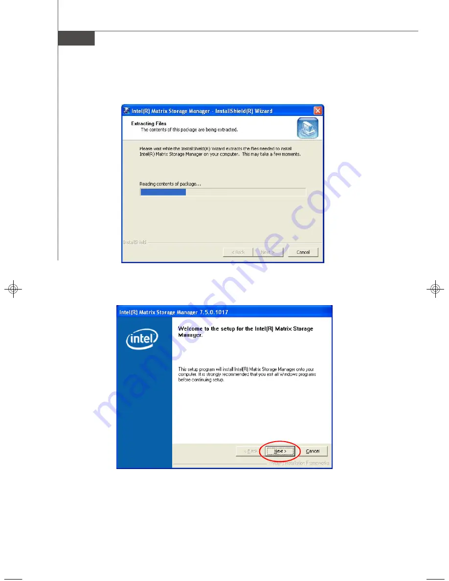
Page 112: ...MS 7356 Mainboard C 12 The InstallShield Wizard will begin automatically for installation showed as following Click on the Next button to proceed the installation in the welcoming window...
Page 113: ...C 13 Intel ICH9R SATA RAID After reading the license agreement in the following window click Yes button to continue The window shows the components to be installed Click Next button to continue...
Page 114: ...6 Mainboard C 14 Once the installation is complete the following window appears The following window appears to show the Readme File Information It shows the system requirements and installation infor...
Page 115: ...the system is first configured in order to take advantage of RAID when upgrading to a second SATA hard drive 1 BIOS must be configured for RAID before installing Windows on the single SATA hard drive...
Page 116: ...m Existing Disk To create a RAID volume from an existing disk choose Action Create RAID Volume from Existing Hard Drive The Create RAID Volume from Existing Hard Drive Wizard pops up to lead you for t...
Page 117: ...ancy will provide you with a realtime duplicate copy of your data Note Only half of the available volume space will be avail able for data storage RAID 5 Useful RAID 5 can be used on three or more dis...
Page 118: ...ypical strip size settings are 4KB For specialized usage models requiring 4KB strips 8KB For specialized usage models requiring 8KB strips 16KB Best for sequential transfers 32KB Good for sequential t...
Page 119: ...r disk the target disk that you wish to use and then click to move it to the Selected field Then click Next to continue Please note that the existing data on the selected hard drive s will be deleted...
Page 120: ...space will be worked as RAID 1 volume which is the new technology called Intel Matrix RAID Then click Next to continue 5 Start Creating RAID Volume from Existing Hard Drive Wizard Before you continue...
Page 121: ...e you can still continue using your computer during the migration process once the migration proc ess starts it cannot be stopped If the migration process gets interrupted and your system is rebooted...
Page 122: ...responds to the current situation Missing Hard Drive Member 1 Make sure the system is powered off 2 Reconnect the hard drive 3 Reboot the system to Windows the rebuild will occur automatically Failed...
Page 123: ...system 6 When prompted to rebuild the RAID volume click Yes 7 The Intel R Storage Utility will be launched Right click the new hard drive and select Rebuild to this Disk The Rebuild Wizard will be lau...