background image

v

Preface  

MS-9A91   

CE Conformity

Hereby, Micro-Star International CO., LTD declares that this device 

is in compliance with the essential safety requirements and other 

relevant provisions set out in the European Directive. 

FCC-A Radio Frequency 

Interference Statement

This equipment has been tested and found to comply with 

the limits for a Class A digital device, pursuant to Part 15 

of the FCC Rules. These limits are designed to provide reasonable protection 

against harmful interference when the equipment is operated in a commercial 

environment. This equipment generates, uses and can radiate radio frequency 

energy and, if not installed and used in accordance with the instruction manual, 

may cause harmful interference to radio communications. Operation of this 

equipment in a residential area is likely to cause harmful interference, in which 

case the user will be required to correct the interference at his own expense.

Notice 1

The changes or modifications not expressly approved by the party responsible for 

compliance could void the user’s authority to operate the equipment.

Notice 2

Shielded interface cables and AC power cord, if any, must be used in order to 

comply with the emission limits.

VOIR LA NOTICE D’INSTALLATION AVANT DE RACCORDER AU RESEAU.

This device complies with Part 15 of the FCC Rules. Operation is subject to the 

following two conditions:
1)  this device may not cause harmful interference, and
2)  this device must accept any interference received, including interference that 

may cause undesired operation.

WEEE Statement

Under the European Union (“EU”) Directive on Waste Electrical and 

Electronic Equipment, Directive 2002/96/EC, which takes effect on 

August 13, 2005, products of “electrical and electronic equipment” 

cannot be discarded as municipal waste anymore and manufacturers 

of covered electronic equipment will be obligated to take back such 

products at the end of their useful life. MSI will comply with the product take back 

requirements at the end of life of MSI-branded products that are sold into the EU. 

You can return these products to local collection points.

Summary of Contents for MS-9A91

Page 1: ...i MS 9A91 Touch Panel PC...

Page 2: ...hout notice Trademarks All trademarks are the properties of their respective owners Revision History Revision Date V1 0 2015 11 Technical Support If a problem arises with your system and no solution c...

Page 3: ...ace anything over the power cord Always Unplug the Power Cord before inserting any add on card or module All cautions and warnings on the equipment should be noted Never pour any liquid into the openi...

Page 4: ...orted household waste Please use the public collection system to return recycle or treat them in compliance with the local regulations Taiwan For better environmental protection waste batteries should...

Page 5: ...ifications not expressly approved by the party responsible for compliance could void the user s authority to operate the equipment Notice 2 Shielded interface cables and AC power cord if any must be u...

Page 6: ...ment and Handling Rule 2011 and prohibits use of lead mercury hexavalent chromium polybrominated biphenyls or polybrominated diphenyl ethers in concentrations exceeding 0 1 weight and 0 01 weight for...

Page 7: ...rarily regulating the permitted limits for a number of hazardous substances in electronic and electric products Vi t Nam RoHS K t ng y 01 12 2012 t t c c c s n ph m do c ng ty MSI s n xu t tu n th Th...

Page 8: ...iv CE Conformity v FCC A Radio Frequency Interference Statement v WEEE Statement v Japan JIS C 0950 Material Declaration vi India RoHS vi Turkey EEE Regulation vi Ukraine Restriction of Hazardous Subs...

Page 9: ...ting and VESA mounting in machine and plant engineering A highly integrated and easy to use platform the MS 9A91 is perfect for factory automation kiosk and more industrial applications like point of...

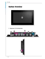
Page 10: ...1 2 Overview System Overview 1 h h System I O Controls 5 2 3 4 6 11 12 13 17 7 8 9 10 15 16 14 10...

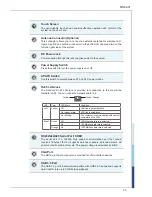
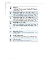
Page 11: ...Network LAN You can connect a network cable to it Yellow Green Orange LED Color LED State Condition Left Yellow Off LAN link is not established On steady state LAN link is established On blinking The...

Page 12: ...IFOs It supports barcode scanners barcode printers bill printers credit card machine etc The power voltage is selectable by BIOS 13 RS232 422 485 Serial Port COM4 The serial port is a 16550A high spee...

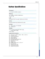
Page 13: ...SSD 1 x mSATA slot Display 15 6 anti glare LED backlit LCD display 1366 x 768 resolution VGA output System I O Controls 3 x Antenna Connectors right x 1 left x 1 rear x 1 1 x DC Power Jack 1 x Power...

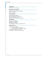
Page 14: ...100 240V 1 3A 50 60Hz Output 12V 7A MAX Each COM port outputs 0 5A Maximum OS Support Windows 7 32 64 Bit Windows 8 1 32 64 Bit Windows 10 32 64 Bit Linux Fedora 20 Ubuntu 13 10 Kernel 3 11 Environme...

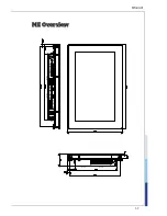
Page 15: ...1 7 MS 9A91 ME Overview...

Page 16: ......

Page 17: ...pter provides you with the information on hardware setup procedures While connecting peripheral devices be careful in holding the devices and use a grounded wrist strap to avoid static electricity 2 G...

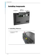
Page 18: ...2 2 Getting Started Installing Components h h Installing Memory 1 Unscrew the SO DIMM compartment...

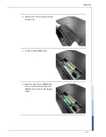
Page 19: ...2 3 MS 9A91 2 Remove the cover and set it aside for later use 3 Locate the SO DIMM slots 4 Align the notch on the DIMM with the key on the slot and insert the DIMM into the slot at a 45 degree angle...

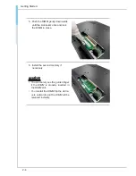
Page 20: ...evers click and lock the DIMM in place 6 Install the second memory if necessary Important You can barely see the golden finger if the DIMM is properly inserted in the DIMM slot To uninstall the DIMM f...

Page 21: ...nstalling mSATA Card 1 Locate the mSATA slot and remove the screw preinstalled on the motherboard 2 Insert the mSATA card into the slot at a 45 degree angle 3 Push the card gently downwards and fasten...

Page 22: ...Installing WiFi Bluetooth Card 1 Locate the screws that secure the system rear cover Unscrew them and keep them for later use 2 Pull the rear cover carefully upwards and set it aside for later use 3 L...

Page 23: ...2 7 MS 9A91 4 Remove the Mini PCIe card screw preinstalled on the motherboard 5 Insert the WiFi card into the slot at a 45 degree angle 6 Push the card gently downwards and fasten it with a screw...

Page 24: ...f the antenna cable to the WiFi card and the other end to the system I O panel 8 Locate the antenna connector on the system I O panel and fasten the antenna to the connector Adjust the antenna s angle...

Page 25: ...2 9 MS 9A91 h h Installing Hard Disk Drive 1 Unscrew the HDD compartment 2 Remove the compartment cover 3 Locate the levers and the retaining lip of the HDD tray...

Page 26: ...fully pull the retaining lip to release the HDD tray out of the bay 5 Fit the HDD into the tray Be sure to put the HDD in the correct orientation and with screw holes aligned 6 Slide the HDD set back...

Page 27: ...2 11 MS 9A91 7 Insert and hide the retaining lip into the gap 8 Screw the HDD compartment to complete the installation...

Page 28: ...2 12 Getting Started Mounting the System h h Panel Mounting...

Page 29: ...2 13 MS 9A91 h h Recommended Opening Size on the Wall Important The recommended maximum wall thickness is 10mm A wall thickness more than 10mm will not mount stably...

Page 30: ...2 14 Getting Started h h VESA Mounting...

Reviews: