


37
Overview of Components
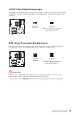
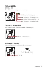
JDASH1 : Tuning Controller connector
This connector is used to connect an optional Tuning Controller module.
1
2
14
13
1
No Pin
2
NC
3
MCU_SMB_SCL_M
4
MCU_SMB_SDA_M
5
VCC5
6
Ground
7
PSIN#_R
8
FP_RST#_R
9
OC_RETRY#
10
OC_FS
11
BLK+
12
BLK-
13
CLRCMOS_EN
14
NC
1
88
Tuning Controller
JDASH1
Debug Code LED
OC
OC Fail Save
OC button-
Tuning Controller cable
OC Retry
Power
Reset
Clear CMOS
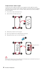
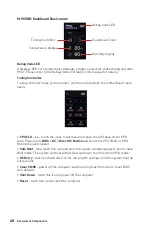
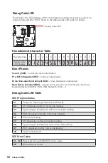
Tuning Controller Module (Optional)
Tuning controller is a multiple functions module that helps you to monitor, control
and overclock the motherboard more easily. Please follow the instructions below to
understand the function of each button on the module.
∙
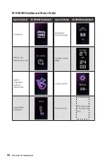
Debug Code LED
- it displays CPU core temperature (default), progress and error
codes during and after POST. Please refer to the Debug Code LED table in this manual
for details.
∙
OC button- / +
-
these buttons are used to decrease/ increase the CPU base clock/
CPU ratio. Please go to
BIOS > OC > Direct OC Button
and select the CPU BCLK or
CPU Ratio to be overclocked.
∙
Reset
- this button allows you to reset the computer.
∙
Power
- this button allows you to power on and off the computer.
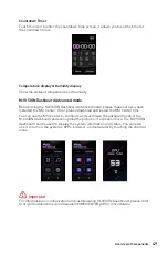
∙
OC Fail Save
- press and hold the button and start the system simultaneously to
boot in Safe Boot mode. The system will boot with default and lower the PCIe (from
CPU) mode.
∙
OC Retry
- press and hold this button for retrying OC settings until the system boot
up successfully.
∙
Clear CMOS
- power off the computer and than long press this button for 5-10
seconds to reset BIOS with defaults.
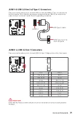
Connecting the JDASH1 and Tuning Controller module
Summary of Contents for MEG Z690 GODLIKE
Page 1: ...I MEG Z690 GODLIKE Motherboard User Guide...
Page 2: ...II English...
Page 11: ...XI Full armor kit x3 x2...
Page 12: ...XII Connecting Peripheral Devices...
Page 13: ...XIII 4 3 1 2 Power On...
Page 14: ...XIV...
Page 79: ...3 ESD PC ESD ESD PC PC PC PC PC PC 60OC 140OF...
Page 80: ...4...
Page 92: ...16 I O Realtek Realtek PC...
Page 93: ...17 I O 7 1 AUDIO INPUT AUDIO INPUT Rear Front Side Center Subwoofer...
Page 94: ...18 I O 1 2 2 WiFi 1 2 3...
Page 95: ...19 I O Thunderbolt 1 PC thunderbolt thunderbolt Mini DisplayPort USB...
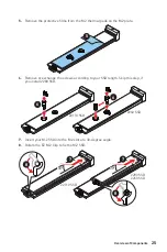
Page 105: ...29 4 M 2 M 2 4 5 M 2 6 M 2 SSD M 2 5 6...
Page 107: ...31 M2_4 M2_5 22110 SSD 2280 SSD 2280 SSD 22110 SSD 2280 SSD 2280 SSD...
Page 111: ...35 JSLOW1 LN2 JLN1 2 Enabled CPU Enabled BIOS POST BIOS POST...
Page 112: ...36 V Check GND V Check VCC GND CPU_VDD2 VCCIN_AUX T_SEN1 2 GND...
Page 114: ...38 4 1 2 3 4 4 5 1 1 1 1 2 3 4 5 5 5 5...
Page 133: ...57 LED 40 S4 AC ACPI PIC AA ACPI APIC CPU CPU MOS PCH 00 99 OS CPU CPU MOS PCH BIOS LED...
Page 141: ...3 ESD ESD ESD PSU PSU 60 C 140 F...
Page 142: ...4...
Page 149: ...11 MSI MSI LAN AI True Color MSI 5 HD 3 10G Super LAN 2 5G LAN LAN Wi Fi Wavy Fin Cross...
Page 154: ...16 Realtek Realtek...
Page 155: ...17 7 1 AUDIO INPUT AUDIO INPUT Rear Front Side Center Subwoofer...
Page 156: ...18 1 2 2 WiFi 1 2 3...
Page 157: ...19 Daisy chain PC Daisy chain daisy chain USB...
Page 167: ...29 4 M 2 M 2 4 5 M 2 6 M 2 SSD M 2 5 6...
Page 169: ...31 M2_4 M2_5 22110 SSD 2280 SSD 2280 SSD 22110 SSD 2280 SSD 2280 SSD...
Page 173: ...35 JSLOW1 LN2 JLN1 2 CPU BIOS POST BIOS POST...
Page 174: ...36 V GND V VCC GND CPU_VDD2 VCCIN_AUX T_SEN1 2 GND Sense...
Page 176: ...38 4 1 2 3 4 5 1 1 1 1 2 3 4 5 5 5 5...
Page 188: ...50 M VISION CPU S4 S5 Disk BIOS Update M VISION 800 480px gif bmp jpg png mp4 M VISION...
Page 203: ...3 ESD 60 C 140 F...
Page 204: ...4...
Page 216: ...16 I O Realtek Realtek...
Page 217: ...17 I O 7 1 AUDIO INPUT AUDIO INPUT Rear Front Side Center Subwoofer...
Page 218: ...18 I O 1 2 WiFi 1 2 3...
Page 219: ...19 I O Daisy chain Thunderbolt PC Thunderbolt Mini DisplayPort USB...
Page 229: ...29 4 M 2 M 2 4 5 M 2 6 M 2 SSD M 2 5 6...
Page 231: ...31 M2_4 M2_5 22110 SSD 2280 SSD 2280 SSD 22110 SSD 2280 SSD 2280 SSD...
Page 235: ...35 JSLOW1 LN2 LN2 JLN1 2 CPU BIOS POST BIOS POST...
Page 236: ...36 V Check Points Lite GND VCC GND CPU_VDD2 VCCIN_AUX T_SEN1 2 GND Sense...
Page 238: ...38 1 2 3 4 5 1 1 1 1 2 3 4 5 5 5 5...
Page 265: ...3 ESD ESD ESD 60 140...
Page 266: ...4...
Page 278: ...16 I O Realtek Realtek...
Page 279: ...17 I O 7 1 AUDIO INPUT AUDIO INPUT Rear Front Side Center Subwoofer...
Page 280: ...18 I O 1 2 WiFi 1 2 3...
Page 291: ...29 4 M 2 M 2 4 5 M 2 6 M 2 M 2 5 6...
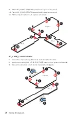
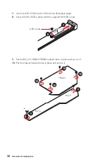
Page 292: ...30 7 M 2 30 M 2 8 M 2 8 5H M 2 30 30 8 8 5H 7 9 M2_4 5 10 10 10 9 9 10 10 M2_4 M2_5...
Page 293: ...31 M2_4 M2_5 22110 2280 2280 22110 2280 2280...
Page 297: ...35 JSLOW1 JLN1 2 CPU BIOS POST BIOS POST...
Page 298: ...36 GND VCC GND CPU_VDD2 VCCIN_AUX T_SEN1 2...
Page 300: ...38 1 2 3 4 5 1 1 1 1 2 3 4 5 5 5 5...
Page 312: ...50 M VISION CPU S4 S5 BIOS M VISION 800 480px gif bmp jpg png mp4 M VISION...
Page 319: ...57 LED 40 S4 AC ACPI PIC AA ACPI APIC CPU CPU MOS PCH 00 99 CPU CPU MOS PCH BIOS LED...


