background image

33

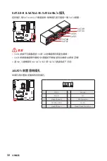
元件總覽

24

13

1

12

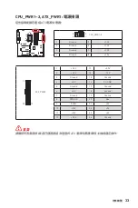
ATX_PWR1

1

+3.3V

13

+3.3V

2

+3.3V

14

-12V

3

Ground

15

Ground

4

+5V

16

PS-ON#

5

Ground

17

Ground

6

+5V

18

Ground

7

Ground

19

Ground

8

PWR OK

20

Res

9

5VSB

21

+5V

10

+12V

22

+5V

11

+12V

23

+5V

12

+3.3V

24

Ground

5

4

1

8

CPU_PWR1~2

1

Ground

5

+12V

2

Ground

6

+12V

3

Ground

7

+12V

4

Ground

8

+12V


重要

請確認所有電源排線,皆已穩固連接到適當的 ATX 電源供應器,確保主機板穩定操作。

CPU_PWR1~2, ATX_PWR1: 電源接頭

這些接頭能讓您連接 ATX 電源供應器。 

Summary of Contents for MEG Z690 GODLIKE

Page 1: ...I MEG Z690 GODLIKE Motherboard User Guide...

Page 2: ...II English...

Page 3: ...ion diagrams about how to install your computer Some of the installations also provide video demonstrations Please link to the URL to watch it with the web browser on your phone or tablet You may have...

Page 4: ...IV Installing a Processor CPU https v youku com v_show id_ XNTE5NDQwNDY2NA html Youtube https youtu be KMf9oIDsGes 1 2 3 6 4 5 7 8 9...

Page 5: ...V Installing DDR5 memory DDR5 DDR5 DDR5 DDR5 DIMMA2 DIMMA2 DIMMB2 DIMMA1 DIMMA2 DIMMB1 DIMMB2 https youtu be XiNmkDNZcZk Youtube https v youku com v_show id_ XNTE5NTg0NDM4NA html...

Page 6: ...LED HDD LED Reset Switch Reserved Power Switch JFP1 1 HDD LED 2 Power LED 3 HDD LED 4 Power LED 5 Reset Switch 6 Power Switch 7 Reset Switch 8 Power Switch 9 Reserved 10 No Pin R E S E T S W P O W E R...

Page 7: ...https v youku com v_show id_ XNDUwMDUyNTkwOA html Youtube 1 Torque 3 kgf cm 3 kgf cm 0 3 N m 2 6 lbf in 2 Important Before installing the motherboard into the case please refer to the M 2 section in t...

Page 8: ...VIII Connecting the Power Connectors http youtu be gkDYyR_83I4 http v youku com v_show id_XNDkzODU0MDQw html Youtube ATX_PWR1 CPU_PWR1 CPU_PWR1 2...

Page 9: ...IX Installing SATA Drives SATA SATA SATA SATA http youtu be RZsMpqxythc http v youku com v_show id_XNDkzODU5MTky html Youtube 1 2 3 4 5...

Page 10: ...X Installing a Graphics Card http youtu be mG0GZpr9w_A http v youku com v_show id_XNDkyOTc3MzQ4 html Youtube 1 2 3 4 5 6...

Page 11: ...XI Full armor kit x3 x2...

Page 12: ...XII Connecting Peripheral Devices...

Page 13: ...XIII 4 3 1 2 Power On...

Page 14: ...XIV...

Page 15: ...1 Front Audio Connector 32 CPU_PWR1 2 ATX_PWR1 Power Connectors 33 JFP1 JFP2 Front Panel Connectors 34 W_FLOW1 Water Flow Meter Connector 34 JSLOW1 Slow Mode Booting Jumper 35 JLN1 2 Low Temperature B...

Page 16: ...EZ Debug LED 51 JPWRLED1 LED power input 51 LED_SW1 EZ LED Control 51 Debug Code LED 52 Hexadecimal Character Table 52 Boot Phases 52 Debug Code LED Table 52 SEC Progress Codes 52 Installing OS Driver...

Page 17: ...e computer before installation is completed This could cause permanent damage to the components as well as injury to the user If you need help during any installation step please consult a certified c...

Page 18: ...4 Contents Avoid collision notification Protective paint is printed around each screw hole to prevent parts from being scratched...

Page 19: ...el XMP 3 0 OC Supports Dual Controller Dual Channel mode Supports non ECC un buffered memory Please go to www msi com for more information on compatible memory Expansion Slot 3x PCIe x16 slots PCI_E1...

Page 20: ...rt can daisy chain up to three Thunderbolt 4 devices or five Thunderbolt 3 devices Supports up to 8K display need to connect the DisplayPort of the discrete graphics card to the Mini DisplayPort Input...

Page 21: ...upports PCIe 4 0x4 Supports SATA 6Gb s Supports 2260 2280 22110 storage devices M2_6 slot from Z690 chipset Supports PCIe 3 0x4 Supports 2260 2280 storage devices M2_2 M2_4 M2_5 and M2_6 support Intel...

Page 22: ...E The Wireless module is pre installed in the M 2 Key E slot Supports MU MIMO TX RX 2 4GHz 5GHz 6GHz 160MHz up to 2 4Gbps Supports 802 11a b g n ac ax Supports Bluetooth 5 2 Wi Fi 6E 6GHz may depend o...

Page 23: ...or 8x 4 pin system fan connectors 1x Water Flow meter connector 1x Front panel audio connector 2x System panel connectors 1x Chassis Intrusion connector 2x 2 pin Thermal Sensors connectors 1xTPM modul...

Page 24: ...fan speed control Form Factor E ATX Form Factor 12 in x 12 in 30 5 cm x 31 0 cm BIOS Features Dual BIOS 2x 256 Mb flash UEFI AMI BIOS ACPI 6 4 SMBIOS 3 4 Multi language Software Drivers MSI Center Int...

Page 25: ...es Frozr AI Cooling User Scenario True Color Live Update Hardware Monitoring Super Charger Speed Up Smart Image Finder MSI Companion Special Features Audio Audio Boost 5 HD Nahimic 3 Sound Tune Networ...

Page 26: ...CORSAIR RGB Mystic Light SYNC Ambient Devices Support EZ LED Control EZ DEBUG LED Performance Lightning Gen 5 PCI_E1 PCI_E2 M2_3 Lightning Gen 4 PCI_E3 M2_1 2 M2_4 5 Multi GPU SLI CrossFire Memory Boo...

Page 27: ...on MSI Center Click BIOS 5 EZ M 2 Clip Frozr AI Cooling System Saver Flash BIOS Button EZ LED Control EZ Dubug LED Duet Display App Player Tile JCORSAIR1 Connector Specification Supporting CORSAIR RGB...

Page 28: ...bles 3 LED JRGB Y cable 1 LED JCORSAIR cable 1 LED JRAINBOW cable 2 M VISION Dashborad Cable 1 Front Panel Cable 1 Thermistor cable 2 DP to Mini DP cable 2 Accessories Wi Fi antenna 1 Case badge 1 M 2...

Page 29: ...e Speaker Out Line Out Front Speaker Out Mic In connected Blank empty Thunderbolt 4 USB C Mini DisplayPort Input for Thunderbolt passthrough USB 3 2 Gen 2 10Gbps Type A 2 5 Gbps LAN 10 Gbps LAN Audio...

Page 30: ...rols the volume or balance the right left side of the speakers that you plugged in front or rear panel by adjust the bar Jack Status depicts all render and capture devices currently connected with you...

Page 31: ...Rear I O Panel Audio jacks to headphone and microphone diagram Audio jacks to stereo speakers diagram Audio jacks to 7 1 channel speakers diagram AUDIO INPUT AUDIO INPUT Rear Front Side Center Subwoof...

Page 32: ...18 Rear I O Panel Installing Antennas 1 Combine the antenna with the base 2 Screw two antenna cables tight to the WiFi antenna connectors as shown 1 2 3 Place the antenna as high as possible...

Page 33: ...ith only one output terminal Daisy chain allows you to connect multiple thunderbolt devices to a single thunderbolt port on the back panel You can also daisy chain monitor by connecting graphics card...

Page 34: ...5 6 SATA 7 8 JBAT1 JSLOW1 CPU_FAN1 SYS_FAN1 SYS_FAN3 PUMP_FAN1 PCI_E1 PCI_E2 M2_4 M2_3 M2_2 M2_5 M2_1 PCI_E3 JAUD1 JDASH1 W_FLOW1 JUSB6 CPU Socket CPU_PWR1 CPU_PWR2 SYS_FAN4 SYS_FAN5 M_SW1 JRAINBOW2 J...

Page 35: ...mal tape between the CPU and the heatsink to enhance heat dissipation Whenever the CPU is not installed always protect the CPU socket pins by covering the socket with the plastic cap If you purchased...

Page 36: ...hen overclocking due to the memory frequency operates dependent on its Serial Presence Detect SPD Go to BIOS and find the DRAM Frequency to set the memory frequency if you want to operate the memory a...

Page 37: ...ng or removing expansion cards always turn off the power supply and unplug the power supply power cable from the power outlet Read the expansion card s documentation to check for any necessary additio...

Page 38: ...2 SATA SSD in the M2_4 slot PCI_E3 will run at x1 speed and M2_4 will run at x2 speed when installing PCIe device in PCI_E3 slot and M 2 PCIe SSD in M2_4 slot simultaneously M2_1 M2_3 slot Installatio...

Page 39: ...M 2 plate 5 6 Remove or exchange the screws according to your SSD length Skip this step if you install 2280 SSD 6 6 22110 SSD 2260 SSD 7 Insert your M 2 SSD into the M 2 slot at a 30 degree angle 8 R...

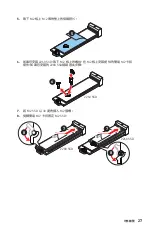
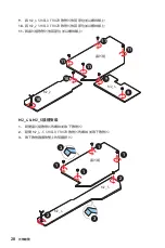
Page 40: ...e and secure it 10 10 10 9 9 10 11 11 M2_1 chipset M2_3 M2_2 M2_6 slot Installation 1 Loosen the screws of Chipset heatsink and remove the heatsink 2 Loosen the screws of M2_2 SHIELD FROZR heatsink an...

Page 41: ...ou install 2260 SSD remove the screw from the M 2 plate and then install supplied EZ M 2 Clip kit on the M 2 plate Skip this step if you install 2280 SSD 6 2260 SSD 7 Insert your M 2 SSD into the M 2...

Page 42: ...1 Put the chipset heatsink back in place and secure it 11 11 10 9 9 10 11 11 M2_2 chipset M2_6 M2_4 M2_5 slot installation 1 Loosen the screws of Chipset heatsink and remove the heatsink 2 Loosen the...

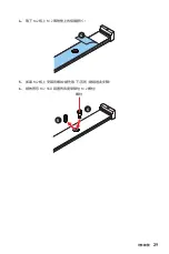
Page 43: ...protective films from the M 2 thermal pads on the M 2 plate 4 5 If there is a screw installed on the M 2 plate remove it first otherwise please skip this step 6 Secure the supplied M 2 standoff accord...

Page 44: ...t at a 30 degree angle 8 Secure the M 2 SSD in place with the supplied M 2 8 5H screw 30 30 8 8 5H screw 7 9 Put the M2_4 5 SHIELD FROZR heatsink back in place and secure it 10 Put the chipset heatsin...

Page 45: ...31 Overview of Components Ways to install M2_4 M2_5 22110 SSD 2280 SSD 2280 SSD 22110 SSD 2280 SSD 2280 SSD...

Page 46: ...ansmission otherwise SATA cables have identical plugs on either sides of the cable However it is recommended that the flat connector be connected to the motherboard for space saving purposes SATA7 wil...

Page 47: ...9 5VSB 21 5V 10 12V 22 5V 11 12V 23 5V 12 3 3V 24 Ground 5 4 1 8 CPU_PWR1 2 1 Ground 5 12V 2 Ground 6 12V 3 Ground 7 12V 4 Ground 8 12V Important Make sure that all the power cables are securely conn...

Page 48: ...ower Switch JFP1 1 HDD LED 2 Power LED 3 HDD LED 4 Power LED 5 Reset Switch 6 Power Switch 7 Reset Switch 8 Power Switch 9 Reserved 10 No Pin 1 JFP2 Speaker Buzzer 1 Speaker 2 Buzzer 3 Buzzer 4 Speake...

Page 49: ...sed for liquid nitrogen cooling system to boot at an extreme low temperature Try to set it Enabled to increase the boot success rate Important Users will try extreme low temperature overclocking at th...

Page 50: ...ages To measure voltage place test leads on the GND screw mounting hole and a specific V Check Point Please refer to the manual of your multimeter for more information VCC GND CPU_VDD2 VCCIN_AUX T_SEN...

Page 51: ...LED it displays CPU core temperature default progress and error codes during and after POST Please refer to the Debug Code LED table in this manual for details OC button these buttons are used to decr...

Page 52: ...ver of module Please follow the instructions below to stick the magnets 1 Loosen the screws of the back cover 2 Open and turn the back cover over 3 Remove the sticker from the magnet 4 Stick four magn...

Page 53: ...3 2 Gen 1 Connectors These connectors allow you to connect USB 3 2 Gen 1 5Gbps ports on the front panel Important Note that the Power and Ground pins must be connected correctly to avoid possible dam...

Page 54: ...to avoid possible damage In order to recharge your iPad iPhone and iPod through USB ports please install MSI Center utility 1 2 12 11 1 SPI Power 2 SPI Chip Select 3 Master In Slave Out SPI Data 4 Mas...

Page 55: ...y Switching fan mode and adjusting fan speed You can switch between PWM mode and DC mode and adjust fan speed in BIOS HARDWARE MONITOR Important Make sure fans are working properly after switching the...

Page 56: ...nfiguration 4 Set Chassis Intrusion to Enabled 5 Press F10 to save and exit and then press the Enter key to select Yes 6 Once the chassis cover is opened again a warning message will be displayed on s...

Page 57: ...ord 2 Use a jumper cap to short JBAT1 for about 5 10 seconds 3 Remove the jumper cap from JBAT1 4 Plug the power cord and Power on the computer BIOS_SW1 Multi BIOS Switch This motherboard has two buil...

Page 58: ...from the power outlet before installing or removing the RGB LED strip Please use MSI s software to control the extended LED strip JRGB1 RGB LED connector The JRGB connector allows you to connect the...

Page 59: ...s up to 200 LEDs Always turn off the power supply and unplug the power cord from the power outlet before installing or removing the RGB LED strip Please use MSI s software to control the extended LED...

Page 60: ...Important Fans must start at 1 and continue in series 1 2 3 4 5 6 Any fan not connected in series will break communication and the RGB LED lighting function will not work Quantity of RGB LED Fans or R...

Page 61: ...mp4 animation file M VISION Dashboard Connecting the M VISION Dashboard You can also remove the M VISION Dashboard from the motherboard and it still can be activated Please follow the steps below to c...

Page 62: ...ily CPU CLK touch the icons to decrease increase the CPU base clock CPU ratio Please go to BIOS OC Direct OC Button and select the CPU BCLK or CPU Ratio to be overclocked Safe Boot long touch this ico...

Page 63: ...Center If not please download and install the MSI Center first You can use the MSI Center to configure and customize the advanced mode of the M VISION dashboard and even upload the pictures or animat...

Page 64: ...board Power On CPU is not detected or fail S4 S5 Suspend to Disk Shutdown Flash BIOS Update System Status M VISION Dashboard Hardware Monitor page System Clock page Live weather User profile 800 480px...

Page 65: ...ndicates DRAM is not detected or fail CPU indicates CPU is not detected or fail VGA indicates GPU is not detected or fail JPWRLED1 LED power input This connector is used by retailers to demonstrate on...

Page 66: ...The Debug Code LED displays CPU core temperature default progress and error codes during and after POST Refer to the Debug Code LED table for details Debug Code LED Table SEC Progress Codes 01 Power...

Page 67: ...3 CPU post memory initialization Cache initialization 34 CPU post memory initialization Application Processor s AP initialization 35 CPU post memory initialization Boot Strap Processor BSP selection 3...

Page 68: ...is started 6B 6F System Agent DXE initialization System Agent module specific 70 PCH DXE initialization is started 71 PCH DXE SMM initialization is started 72 PCH devices initialization 73 77 PCH DXE...

Page 69: ...ddress MAP End B2 Legacy Option ROM Initialization B3 System Reset B4 USB hot plug B5 PCI bus hot plug B6 Clean up of NVRAM B7 Configuration Reset reset of NVRAM settings B8 BF Reserved for future AMI...

Page 70: ...Codes F0 Recovery condition triggered by firmware Auto recovery F1 Recovery condition triggered by user Forced recovery F2 Recovery process started F3 Recovery firmware image is found F4 Recovery fir...

Page 71: ...em has transitioned into ACPI mode Interrupt controller is in PIC mode AA System has transitioned into ACPI mode Interrupt controller is in APIC mode CPU core CPU socket System MOS PCH Temperature 00...

Page 72: ...t Run DVDSetup exe to open the installer If you turn off the AutoPlay feature from the Windows Control Panel you can still manually execute the DVDSetup exe from the root path of the MSI USB Drive 4 T...

Page 73: ...ns Supports full capabilities of new devices new devices may not provide backward compatibility Supports secure startup UEFI can check the validity of the operating system to ensure that no malware ta...

Page 74: ...ress DEL key to enter Setup Menu F11 to enter Boot Menu message appears on the screen during the boot process Function key F1 General Help list F2 Add Remove a favorite item F3 Enter Favorites menu F4...

Page 75: ...OS file into the USB flash drive Updating BIOS 1 Switch to the target BIOS ROM by Multi BIOS switch Please skip this step if your motherboard doesn t has this switch 2 Insert the USB flash drive that...

Page 76: ...system will automatically restart to update BIOS 6 After the flashing process is 100 completed the system will restart automatically Updating BIOS with Flash BIOS Button 1 Please download the latest B...

Page 77: ...8 SATAA B SATA 6Gb s 32 JAUD1 32 CPU_PWR1 2 ATX_PWR1 33 JFP1 JFP2 34 W_FLOW1 34 JSLOW1 35 JLN1 2 35 T_SEN1 2 36 V Check 36 JDASH1 37 JUSB1 2 USB 3 2 Gen 2x2 Type C 39 JUSB3 4 USB 3 2 Gen 1 39 JUSB5 6...

Page 78: ...ION Dashboard 47 M_SW1 M VISION 47 M VISION Dashboard 50 LED 51 EZ Debug LED 51 JPWRLED1 LED 51 LED_SW1 EZ LED 51 LED 52 16 52 52 LED 52 SEC 52 OS MSI Center 58 Windows 10 Windows 11 58 58 MSI Center...

Page 79: ...3 ESD PC ESD ESD PC PC PC PC PC PC 60OC 140OF...

Page 80: ...4...

Page 81: ...DPC 1R 6666 MHz 1DPC 2R 5600 MHz 2DPC 1R 4000 MHz 2DPC 2R 4000 MHz Intel XMP 3 0 OC non ECC un buffered www msi com PCIe x16 x3 PCI_E1 PCIe 5 0 x16 CPU PCI_E2 PCIe 5 0 x8 CPU PCI_E3 PCIe 4 0 x4 Z690 P...

Page 82: ...bps USB4 20Gbps USB 3 2 10Gbps 5V 3A 15W 3 Thunderbolt 4 5 Thunderbolt 3 8K DisplayPort Mini DisplayPort USB Intel Z690 USB 3 2 Gen 2x2 20Gbps Type C x2 USB USB 3 2 Gen 2 10Gbps x4 Hub GL3590 USB 3 2...

Page 83: ...e 5 0x4 2260 2280 22110 M2_4 Z690 PCIe 4 0x4 SATA 6Gb s 2280 22110 M2_5 Z690 PCIe 4 0x4 SATA 6Gb s 2260 2280 22110 M2_6 Z690 PCIe 3 0x4 2260 2280 M2_2 M2_4 M2_5 M2_6 Intel Optane Intel Core Intel Smar...

Page 84: ...ES9218PQ DAC HPA 7 1 HD S PDIF LAN Bluetooth Intel WiFi 6E M 2 Key E MU MIMO TX RX 2 4GHz 5GHz 6GHz 160MHz 2 4Gbps 802 11 a b g n ac ax Bluetooth 5 2 Wi Fi 6E 6GHz Windows 10 21H1 Windows 11 Bluetooth...

Page 85: ...Gbps Type C x2 USB 3 2 Gen 1 5Gbps x2 4 USB 3 2 Gen 1 5Gbps USB 2 0 x2 4 USB 2 0 4 CPU x1 4 x1 4 x8 x1 x1 x2 x1 2 x2 TPM x1 x1 x1 x2 CMOS x1 LED 2 Digit Debug Code LED x1 EZ Debug LED x4 4 RGB LED x1...

Page 86: ...31 0 cm BIOS Dual BIOS 256 Mb x2 UEFI AMI BIOS ACPI 6 4 SMBIOS 3 4 MSI Center Intel Extreme Tuning Utility Nahimic MSI APP Player BlueStacks Open Broadcaster Software OBS CPU Z MSI GAMING Google Chro...

Page 87: ...lights LAN Manager Mystic Light Ambient Devices Frozr AI Cooling User Scenario True Color Live Update Hardware Monitoring Super Charger Speed Up Smart Image Finder MSI Companion MSI Audio Boost 5 HD N...

Page 88: ...ystic Light SYNC Ambient EZ LED EZ DEBUG LED Lightning Gen 5 PCI_E1 PCI_E2 M2_3 Lightning Gen 4 PCI_E3 M2_1 2 M2_4 5 GPU SLI CrossFire Memory Boost Memory Force Core Boost Game Boost OC Engine Thunder...

Page 89: ...O M VISION Dashboard MSI Center Click BIOS 5 EZ M 2 Frozr AI System Saver Flash BIOS EZ LED EZ Debug LED Duet Display App Player Tile JCORSAIR1 CORSAIR RGB Lighting Node PRO LED 20 LED 8 20 HD120 RGB...

Page 90: ...14 MEG Z690 GODLIKE 1 DIY 1 USB 1 SATA 6Gb s 3 LED JRGB Y 1 LED JCORSAIR 1 LED JRAINBOW 2 M VISION Dashboard 1 1 2 DP Mini DP 2 Wi Fi 1 1 M 2 2 2 DIY 1 MEG 1 SATA 1 1 1 1 1 1...

Page 91: ...4 USB C Mini DisplayPort Thunderbolt USB 3 2 Gen 2 10Gbps Type A 2 5 Gbps LAN 10 Gbps LAN S PDIF CMOS Wi Fi Flash BIOS Flash BIOS M VISION Dashboard LED Off 2 5Gb LAN 10Gb LAN LED 2 5 Gbps LAN 10 Gbps...

Page 92: ...16 I O Realtek Realtek PC...

Page 93: ...17 I O 7 1 AUDIO INPUT AUDIO INPUT Rear Front Side Center Subwoofer...

Page 94: ...18 I O 1 2 2 WiFi 1 2 3...

Page 95: ...19 I O Thunderbolt 1 PC thunderbolt thunderbolt Mini DisplayPort USB...

Page 96: ...SLOW1 CPU_FAN1 SYS_FAN1 SYS_FAN3 PUMP_FAN1 PCI_E1 PCI_E2 M2_4 M2_3 M2_2 M2_5 M2_1 PCI_E3 JAUD1 JDASH1 W_FLOW1 JUSB6 CPU CPU_PWR1 CPU_PWR2 SYS_FAN4 SYS_FAN5 M_SW1 JRAINBOW2 JCORSAIR1 POWER1 JTPM1 LED_S...

Page 97: ...21 CPU CPU CPU CPU CPU CPU CPU CPU CPU CPU CPU CPU CPU CPU CPU CPU CPU CPU CPU CPU CPU MSI CPU LGA1700 CPU LGA1700 CPU 4 1 CPU DIMM 50 8 mm...

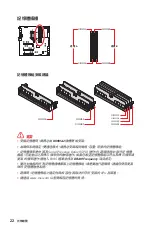
Page 98: ...22 DIMM DIMMA1 DIMMB1 A B DIMMA2 DIMMB2 DIMMA2 SPD BIOS DRAM Frequency DIMM CPU www msi com DIMMB2 DIMMB2 DIMMB1 DIMMA2 DIMMA2 DIMMA2 DIMMA1...

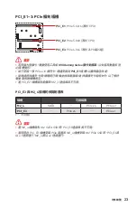
Page 99: ...E2 PCIe 5 0 x8 CPU PCI_E3 PCIe 4 0 x4 Z690 MSI Gaming Series Graphics Card Bolster PCIe x16 PCI_E1 PCI_E2 M2_3 M2_4 SATA PCIe x4 PCIe x2 PCI_E3 PCIe x4 PCIe x1 PCI_E3 M2_4 M 2 SATA SSD M2_4 PCI_E3 PCI...

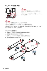
Page 100: ...5 M2_4 Intel RST UEFI ROM PCIe M 2 SSD M2_2 M2_4 M2_5 M2_6 Intel Optane PCI_E2 M2_3 M 2 SATA SSD M2_4 PCI_E3 PCIe PCI_E3 M 2 PCIe SSD M2_4 PCI_E3 x1 M2_4 x2 M2_1 M2_3 1 M2_1 SHIELD FROZR 2 3 M2_3 SHIE...

Page 101: ...25 5 M 2 M 2 5 6 SSD 2280 SSD 6 6 22110 SSD 2260 SSD 7 30 M 2 SSD M 2 8 EZ M 2 M 2 SSD 30 30 30 30 7 7 8 8 22110 SSD 2280 SSD 2260 SSD...

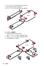
Page 102: ...26 9 M2_3 SHIELD FROZR 10 11 M2_1 SHIELD FROZR 10 10 10 9 9 10 11 11 M2_1 M2_3 M2_2 M2_6 1 2 M2_2 SHIELD FROZR 3 M2_6 SHIELD FROZR 4 1 1 2 3 3 4 4 4 2 1 1 M2_2 M2_6...

Page 103: ...27 5 M 2 M 2 5 6 2260 SSD M 2 EZ M 2 M 2 2280 SSD 6 2260 SSD 7 30 M 2 SSD M 2 8 EZ M 2 M 2 SSD 30 30 30 30 2280 SSD 2260 SSD 8 7 7 8...

Page 104: ...28 9 M2_6 SHIELD FROZR 10 M2_2 SHIELD FROZR 11 11 11 10 9 9 10 11 11 M2_2 M2_6 M2_4 M2_5 1 2 M2_4 5 SHIELD FROZR 3 1 1 2 3 3 2 1 1 M2_4 M2_5...

Page 105: ...29 4 M 2 M 2 4 5 M 2 6 M 2 SSD M 2 5 6...

Page 106: ...30 7 30 M 2 SSD M 2 8 M 2 8 5H M 2 SSD 30 30 8 8 5H 7 9 M2_4 5 SHIELD FROZR 10 10 10 9 9 10 10 M2_4 M2_5...

Page 107: ...31 M2_4 M2_5 22110 SSD 2280 SSD 2280 SSD 22110 SSD 2280 SSD 2280 SSD...

Page 108: ...s SATA 6Gb s SATA SATAA SATA5 SATA7 SATAB SATA6 SATA8 SATA 90 SATA M 2 SATA SSD M2_5 SATA7 JAUD1 1 2 10 9 1 MIC L 2 Ground 3 MIC R 4 NC 5 Head Phone R 6 MIC Detection 7 SENSE_SEND 8 No Pin 9 Head Phon...

Page 109: ...d 15 Ground 4 5V 16 PS ON 5 Ground 17 Ground 6 5V 18 Ground 7 Ground 19 Ground 8 PWR OK 20 Res 9 5VSB 21 5V 10 12V 22 5V 11 12V 23 5V 12 3 3V 24 Ground 5 4 1 8 CPU_PWR1 2 1 Ground 5 12V 2 Ground 6 12V...

Page 110: ...Reserved Power Switch JFP1 1 HDD LED 2 Power LED 3 HDD LED 4 Power LED 5 Reset Switch 6 Power Switch 7 Reset Switch 8 Power Switch 9 Reserved 10 No Pin 1 JFP2 Speaker Buzzer 1 Speaker 2 Buzzer 3 Buzze...

Page 111: ...35 JSLOW1 LN2 JLN1 2 Enabled CPU Enabled BIOS POST BIOS POST...

Page 112: ...36 V Check GND V Check VCC GND CPU_VDD2 VCCIN_AUX T_SEN1 2 GND...

Page 113: ...round 7 PSIN _R 8 FP_RST _R 9 OC_RETRY 10 OC_FS 11 BLK 12 BLK 13 CLRCMOS_EN 14 NC 1 88 JDASH1 LED OC OC Fail Save OC OC Retry CMOS LED LED POST POST CPU LED OC CPU CPU BIOS OC Direct OC Button CPU BCL...

Page 114: ...38 4 1 2 3 4 4 5 1 1 1 1 2 3 4 5 5 5 5...

Page 115: ...B 3 2 Gen 1 5Gbps 1 10 11 20 1 Power 11 USB2 0 2 USB3_RX_DN 12 USB2 0 3 USB3_RX_DP 13 Ground 4 Ground 14 USB3_TX_C_DP 5 USB3_TX_C_DN 15 USB3_TX_C_DN 6 USB3_TX_C_DP 16 Ground 7 Ground 17 USB3_RX_DP 8 U...

Page 116: ...9 No Pin 10 NC VCC USB iPad iPhone iPod MSI Center 1 2 12 11 1 SPI Power 2 SPI Chip Select 3 Master In Slave Out SPI Data 4 Master Out Slave In SPI Data 5 Reserved 6 SPI Clock 7 Ground 8 SPI Reset 9...

Page 117: ...DC PWM DC PWM DC BIOS HARDWARE MONITOR PWM DC PWM DC CPU_FAN1 2A 24W PUMP_FAN1 PWM 3A 36W SYS_FAN1 8 2A 12W 1 PWM 1 Ground 2 12V 3 Sense 4 Speed Control Signal 1 DC 1 Ground 2 Voltage Control 3 Sense...

Page 118: ...BIOS SETTINGS Security Chassis Intrusion Configuration 4 Chassis Intrusion Enabled 5 F10 Enter Yes 6 1 BIOS SETTINGS Security Chassis Intrusion Configuration 2 Chassis Intrusion Reset 3 F10 Enter Yes...

Page 119: ...43 JBAT1 CMOS BIOS CMOS CMOS BIOS 1 PC 2 JBAT1 5 10 3 JBAT1 4 BIOS_SW1 BIOS BIOS ROM ROM BIOS LED BIOS ROM CMOS BIOS BIOS B BIOS A BIOS LED BIOS LED BIOS A BIOS B BIOS_SW1 BIOS BIOS_SW1...

Page 120: ...44 RGB 2m 3A 12V 5050 RGB LED 12V G R B RGB LED MSI LED JRGB1 RGB LED JRGB 5050 RGB LED 12V 1 G R B JRGB JRGB 5050 RGB LED 12V 1 1 12V 2 G 3 R 4 B RGB LED 1 1 G R B JRGB RGB LED RGB LED...

Page 121: ...WS2812B RGB ARGB LED 5V Data Ground 20 200 LED RGB LED MSI LED JRAINBOW1 2 RGB ARGB LED JRAINBOW WS2812B RGB ARGB LED 5V JRAINBOW JRAINBOW JRAINBOW LED WS2812B RGB ARGB LED 5V RGB ARGB LED RGB ARGB L...

Page 122: ...MSI CORSAIR RGB LED 1 1 5V 2 Data 3 Ground CORSAIR RGB 1 1 2 3 4 5 6 RGB LED RGB LED RGB LED Lighting PRO CORSAIR RGB LED CORSAIR Lighting Node PRO JCORSAIR1 SYS_FAN SYS_FAN SYS_FAN SYS_FAN SYS_FAN SY...

Page 123: ...SION Dashboard gif bmp png jpg mp4 M VISION Dashboard M VISION Dashboard M VISION Dashboard M VISION Dashboard 1 M VISION Dashboard 2 M VISION M VISION Dashboard USB M VISION Dashboard 3 M VISION M_SW...

Page 124: ...48 M VISION Dashboard LED LED LED POST POST CPU LED CPU CLK CPU CPU BIOS OC Direct OC Button CPU BCLK CPU Ratio PCIe CPU OC Retry OC CMOS PC BIOS PC PC...

Page 125: ...49 M VISION Dashboard M VISION Dashboard MSI Center MSI Center M VISION Dashboard M VISION Dashboard APP M VISION Dashboard http download msi com manual mb MSICENTER pdf...

Page 126: ...50 M VISION Dashboard CPU S4 S5 Flash BIOS M VISION Dashboard 800 480px gif bmp jpg png mp4 M VISION Dashboard...

Page 127: ...51 LED EZ Debug LED LED LED BOOT DDR DRAM CPU CPU VGA GPU JPWRLED1 LED LED JPWRLED1 LED LED_SW1 EZ LED LED LED_SW1 LED_OFF LED_ON...

Page 128: ...2 3 4 5 6 7 8 9 A B C D E F Security SEC Pre EFI Initialization PEI Driver Execution Environment DXE Boot Device Selection BDS pre OS CD DVD HDD USB Shell LED LED LED POST POST CPU LED LED SEC 01 02 A...

Page 129: ...memory PCH PCH 2B SPD Serial Presence Detect 2C 2D 2E 2F 31 32 CPU post memory 33 CPU post memory 34 CPU post memory AP 35 CPU post memory BSP 36 CPU post memory SMM 37 Post Memory 38 3A Post Memory 3...

Page 130: ...PU DXE 64 67 CPU DXE CPU 68 PCI 69 DXE 6A DXE SMM 6B 6F DXE 70 PCH DXE 71 PCH DXE SMM 72 PCH 73 77 PCH DXE PCH 78 ACPI 79 CSM 7A 7F DXE 90 91 92 PCI 93 PCI 94 PCI Enumeration 32 95 PCI 96 PCI 97 98 99...

Page 131: ...A3 IDE A4 SCSI A5 SCSI A6 SCSI A7 SCSI A8 A9 AB AD AE AF B0 MAP B1 MAP B2 Option ROM B3 B4 USB B5 PCI B6 NVRAM B7 NVRAM B8 BF DXE D0 CPU D1 D2 PCH D3 D4 PCI D5 Option ROM D6 D7 D8 D9 LoadImage DA Sta...

Page 132: ...S3 E0 S3 S3 Resume PPI DXE IPL E1 S3 E2 E3 OS S3 wake E4 E7 S3 E8 S3 E9 S3 PPI EA S3 EB S3 OS Wake EC EF F0 F1 F2 F3 F4 F5 F7 F8 PPI F9 FA FB FF ACPI OS ACPI 01 S1 02 S2 03 S3 04 S4 05 S5 10 S1 20 S2...

Page 133: ...57 LED 40 S4 AC ACPI PIC AA ACPI APIC CPU CPU MOS PCH 00 99 OS CPU CPU MOS PCH BIOS LED...

Page 134: ...6 Press any key to boot from CD or DVD Enter 7 Windows 10 Windows 11 1 Windows 10 Windows 11 2 MSI USB USB 3 Select to choose what happens with this disc Run DVDSetup exe Windows MSI USB DVDSetup exe...

Page 135: ...S BIOS MSI UEFI BIOS UEFI BIOS UEFI BIOS UEFI UEFI BIOS POST CSM 2 TB GUID Partition Table GPT 4 UEFI UEFI 32 Windows Windows 10 Windows 11 64 GOP Graphics Output Protocol GOP UEFI CPU BIOS 1 PC 2 Pre...

Page 136: ...Press DEL key to enter Setup Menu F11 to enter Boot Menu Delete F1 F2 Favorites F3 Favorites F4 CPU F5 Memory Z F6 optimized defaults F7 EZ F8 OC F9 OC F10 F12 USB FAT FAT32 Ctrl F F10 Yes No BIOS BI...

Page 137: ...optimized defaults CMOS CMOS PC BIOS CMOS BIOS M FLASH BIOS MSI WEB BIOS USB BIOS 1 BIOS BIOS ROM 2 BIOS USB USB 3 POST Ctrl F5 Yes Press Ctrl F5 to activate M Flash for BIOS update POST Delete BIOS M...

Page 138: ...BIOS LAN BIOS 1 MSI CENTER Support 2 Live Update Advanced 3 BIOS Install 4 Install 5 BIOS 6 Flash BIOS BIOS 1 MSI WEB BIOS 2 BIOS MSI ROM USB 3 CPU_PWR1 ATX_PWR1 4 MSI ROM USB I O Flash BIOS 5 Flash B...

Page 139: ...24 SATA5 8 SATAA B SATA 6Gb s 32 JAUD1 32 33 JFP1 JFP2 34 W_FLOW1 34 JSLOW1 35 JLN1 2 35 T_SEN1 2 36 V 36 JDASH1 37 JUSB1 2 USB 3 2 Gen 2x2 Type C 39 JUSB3 4 USB 3 2 Gen 1 39 JUSB5 6 USB 2 0 40 JTPM1...

Page 140: ...AIR 46 M VISION 47 M_SW1 M VISION 47 M VISION 50 LEDs 51 EZ LED 51 JPWRLED1 LED 51 LED_SW1 EZ LED 51 LED 52 16 52 52 LED 52 SEC 52 ACPI 57 CPU 57 OS MSI 58 Windows 10 Windows 11 58 58 MSI 58 UEFI BIOS...

Page 141: ...3 ESD ESD ESD PSU PSU 60 C 140 F...

Page 142: ...4...

Page 143: ...66 MHz 1DPC 2R 5600 MHz 2DPC 1R 4000 MHz 2DPC 2R 4000 MHz XMP 3 0 OC non ECC un buffered www msi com 3x PCIe x16 PCI_E1 5 0 x16 CPU PCI_E2 5 0 x8 CPU PCI_E3 4 0 x4 Z690 PCI_E2 M2_3 M2_4 M 2 SATA SSD P...

Page 144: ...ps USB4 20Gbps USB 3 2 10Gbps 5V 3A 15W daisy chain 4 3 3 5 8K USB Z690 2x USB 3 2 Gen 2x2 20Gbps Type C 4x USB 3 2 Gen 2 10Gbps Hub GL3590 4x USB 3 2 Gen 2 10Gbps Asmedia 1074 4x USB 3 2 Gen 1 5Gbps...

Page 145: ...CPU PCIe 5 0x4 2260 2280 22110 M2_4 Z690 PCIe 4 0x4 SATA 6Gb s 2280 22110 M2_5 Z690 PCIe 4 0x4 SATA 6Gb s 2260 2280 22110 M2_6 Z690 PCIe 3 0x4 2260 2280 M2_2 M2_4 M2_5 M2_6 Optane Memory Smart Respon...

Page 146: ...V 2 5Gbps LAN Realtek ALC4082 ESS ES9218PQ DAC HPA 7 1 HD S PDIF LAN WiFi 6E M 2 Key E MU MIMO TX RX 2 4GHz 5GHz 6GHz 160MHz 2 4 Gbps 802 11a b g n ac ax 5 2 Wi Fi 6E 6GHz Windows 10 21H1 Windows 11...

Page 147: ...2 Gen 2x2 20Gbps Type C 2x USB 3 2 Gen 1 5Gbps 4 USB 3 2 Gen 1 5Gbps 2x USB 2 0 4 USB 2 0 1x 4 CPU 1x 4 8x 4 1x 1x 2x 1x 2x 2 1xTPM 1x 1x 2x 1x CMOS LED 1x 2 Digit LED 4x EZ LED 1x 4 RGB LED 2x 3 RAIN...

Page 148: ...I O NUVOTON NCT6687D CPU CPU CPU E ATX 12 in x 12 in 30 5 cm x 31 0 cm BIOS BIOS 2x 256 Mb flash UEFI AMI BIOS ACPI 6 4 SMBIOS 3 4 MSI MSI APP Player BlueStacks Open Broadcaster Software OBS CPU Z MS...

Page 149: ...11 MSI MSI LAN AI True Color MSI 5 HD 3 10G Super LAN 2 5G LAN LAN Wi Fi Wavy Fin Cross...

Page 150: ...SFET Choke LED RAINBOW CORSAIR RGB EZ LED EZ LED Gen 5 PCI_E1 PCI_E2 M2_3 Gen 4 PCI_E3 M2_1 2 M2_4 5 GPU SLI CrossFire OC 4 USB 4 0 USB 20G USB 3 2 Gen 2 10G USB Type A C USB Type C CPU PCB 2oz Copper...

Page 151: ...13 PCI E I O M VISION MSI BIOS 5 EZ M 2 AI BIOS EZ LED EZ LED App Player JCORSAIR1 CORSAIR RGB PRO LED LED 8 20 HD120 RGB 6 SP120 RGB 6 LL120 RGB 6...

Page 152: ...14 MEG Z690 GODLIKE 1 DIY 1 USB 1 SATA 6Gb s 3 LED JRGB Y 1 LED JCORSAIR 1 LED JRAINBOW 2 M VISION 1 1 2 DP DP 2 Wi Fi 1 1 M 2 2 2 DIY 1 MEG 1 SATA 1 1 1 1 1 1...

Page 153: ...LED 2 4 6 8 4 USB C 4 USB 3 2 Gen 2 10Gbps Type A 2 5 Gbps LAN 10 Gbps LAN S PDIF CMOS Wi Fi BIOS BIOS M VISION LED 2 5Gb LAN 10Gb LAN LAN LED 2 5 Gbps LAN 10 Gbps LAN 10 Mbps 100 Mbps 1 Gbps 100 Mbp...

Page 154: ...16 Realtek Realtek...

Page 155: ...17 7 1 AUDIO INPUT AUDIO INPUT Rear Front Side Center Subwoofer...

Page 156: ...18 1 2 2 WiFi 1 2 3...

Page 157: ...19 Daisy chain PC Daisy chain daisy chain USB...

Page 158: ...SLOW1 CPU_FAN1 SYS_FAN1 SYS_FAN3 PUMP_FAN1 PCI_E1 PCI_E2 M2_4 M2_3 M2_2 M2_5 M2_1 PCI_E3 JAUD1 JDASH1 W_FLOW1 JUSB6 CPU CPU_PWR1 CPU_PWR2 SYS_FAN4 SYS_FAN5 M_SW1 JRAINBOW2 JCORSAIR1 POWER1 JTPM1 LED_S...

Page 159: ...21 CPU CPU CPU MSI RMA CPU CPU CPU CPU CPU CPU CPU CPU CPU CPU CPU MSI CPU LGA1700 CPU LGA1700 CPU 4 1 CPU 1 CPU DIMM 50 8 mm...

Page 160: ...22 DIMM DIMMA1 DIMMB1 A B DIMMA2 DIMMB2 DIMMA2 Serial Presence Detect SPD BIOS DRAM Frequency DIMM CPU www msi com DIMMB2 DIMMB2 DIMMB1 DIMMA2...

Page 161: ...e 5 0 x16 CPU PCI_E2 PCIe 5 0 x8 CPU PCI_E3 PCIe 4 0 x4 Z690 MSI PCIe x16 PCI_E1 PCI_E2 M2_3 M2_4 SATA PCIe x4 PCIe x2 PCI_E3 PCIe x4 PCIe x1 PCI_E3 M2_4 M2_4 M 2 SATA SSD PCI_E3 PCI_E3 PCIe M2_4 M 2...

Page 162: ...2_6 M2_5 M2_4 RST PCIe M 2 SSD UEFI ROM Optane Memory Ready M2_2 M2_4 M2_5 M2_6 PCI_E2 M2_3 M2_4 M 2 SATA SSD PCI_E3 PCI_E3 PCIe M2_4 M 2 PCIe SSD PCI_E3 x1 M2_4 x2 M2_1 M2_3 1 M2_1 FROZR 2 3 M2_3 FRO...

Page 163: ...25 5 M 2 M 2 5 6 SSD 2280 SSD 6 6 22110 SSD 2260 SSD 7 M 2 SSD 30 M 2 8 EZ M 2 M 2 SSD 30 30 30 30 7 7 8 8 22110 SSD 2280 SSD 2260 SSD...

Page 164: ...26 9 M2_3 FROZR 10 11 M2_1 FROZR 10 10 10 9 9 10 11 11 M2_1 M2_3 M2_2 M2_6 1 2 M2_2 FROZR 3 M2_6 FROZR 4 1 1 2 3 3 4 4 4 2 1 1 M2_2 M2_6...

Page 165: ...27 5 M 2 M 2 5 6 2260 SSD M 2 M 2 EZ M 2 2280 SSD 6 2260 SSD 7 M 2 SSD 30 M 2 8 EZ M 2 M 2 SSD 30 30 30 30 2280 SSD 2260 SSD 8 7 7 8...

Page 166: ...28 9 M2_6 FROZR 10 M2_2 FROZR 11 11 11 10 9 9 10 11 11 M2_2 M2_6 M2_4 M2_5 1 2 M2_4 5 FROZR 3 1 1 2 3 3 2 1 1 M2_4 M2_5...

Page 167: ...29 4 M 2 M 2 4 5 M 2 6 M 2 SSD M 2 5 6...

Page 168: ...30 7 M 2 SSD M 2 30 8 M 2 8 5H M 2 SSD 30 30 8 8 5H 7 9 M2_4 5 FROZR 10 10 10 9 9 10 10 M2_4 M2_5...

Page 169: ...31 M2_4 M2_5 22110 SSD 2280 SSD 2280 SSD 22110 SSD 2280 SSD 2280 SSD...

Page 170: ...s SATA 6Gb s SATA SATAA SATA5 SATA7 SATAB SATA6 SATA8 SATA 90 SATA M2_5 M 2 SATA SSD SATA7 JAUD1 1 2 10 9 1 MIC L 2 Ground 3 MIC R 4 NC 5 Head Phone R 6 MIC Detection 7 SENSE_SEND 8 No Pin 9 Head Phon...

Page 171: ...2V 3 Ground 15 Ground 4 5V 16 PS ON 5 Ground 17 Ground 6 5V 18 Ground 7 Ground 19 Ground 8 PWR OK 20 Res 9 5VSB 21 5V 10 12V 22 5V 11 12V 23 5V 12 3 3V 24 Ground 5 4 1 8 CPU_PWR1 2 1 Ground 5 12V 2 Gr...

Page 172: ...erved JFP1 1 HDD LED 2 Power LED 3 HDD LED 4 Power LED 5 Reset Switch 6 Power Switch 7 Reset Switch 8 Power Switch 9 Reserved 10 No Pin 1 JFP2 Speaker Buzzer 1 Speaker 2 Buzzer 3 Buzzer 4 Speaker W_FL...

Page 173: ...35 JSLOW1 LN2 JLN1 2 CPU BIOS POST BIOS POST...

Page 174: ...36 V GND V VCC GND CPU_VDD2 VCCIN_AUX T_SEN1 2 GND Sense...

Page 175: ..._SMB_SDA_M 5 VCC5 6 Ground 7 PSIN _R 8 FP_RST _R 9 OC_RETRY 10 OC_FS 11 BLK 12 BLK 13 CLRCMOS_EN 14 NC 1 88 JDASH1 LED OC OC Fail Save OC OC CMOS LED CPU POST LED OC CPU CPU BIOS OC Direct OC CPU BCLK...

Page 176: ...38 4 1 2 3 4 5 1 1 1 1 2 3 4 5 5 5 5...

Page 177: ...1 USB 3 2 Gen 1 5Gbps 1 10 11 20 1 Power 11 USB2 0 2 USB3_RX_DN 12 USB2 0 3 USB3_RX_DP 13 Ground 4 Ground 14 USB3_TX_C_DP 5 USB3_TX_C_DN 15 USB3_TX_C_DN 6 USB3_TX_C_DP 16 Ground 7 Ground 17 USB3_RX_D...

Page 178: ...und 9 No Pin 10 NC VCC USB iPad iPhone iPod MSI 1 2 12 11 1 SPI Power 2 SPI Chip Select 3 Master In Slave Out SPI Data 4 Master Out Slave In SPI Data 5 Reserved 6 SPI Clock 7 Ground 8 SPI Reset 9 Rese...

Page 179: ...n DC PWM 12V DC PWM DC PWM DC PWM DC BIOS HARDWARE MONITOR PWM DC CPU_FAN1 2A 24W PUMP_FAN1 PWM 3A 36W SYS_FAN1 8 2A 12W 1 PWM 1 Ground 2 12V 3 Sense 4 Speed Control Signal 1 DC 1 Ground 2 Voltage Con...

Page 180: ...3 BIOS SETTINGS Security Chassis Intrusion Configuration 4 Chassis Intrusion Enabled 5 F10 Enter Yes 6 1 BIOS SETTINGS Security Chassis Intrusion Configuration 2 Chassis Intrusion Reset 3 F10 Enter Y...

Page 181: ...43 JBAT1 CMOS Reset BIOS CMOS CMOS BIOS 1 2 JBAT1 5 10 3 JBAT1 4 BIOS_SW1 BIOS 2 BIOS ROM BIOS LED BIOS ROM CMOS BIOS BIOS B BIOS A BIOS BIOS BIOS A BIOS B BIOS_SW1 BIOS BIOS_SW1...

Page 182: ...44 JRGB 3A 12V 2 5050 RGB LED 12V G R B RGB LED MSI LED JRGB1 RGB LED JRGB 5050 RGB LED 1 G R B JRGB JRGB 5050 RGB LED 12V 1 1 12V 2 G 3 R 4 B RGB LED 1 1 G R B JRGB RGB LED RGB LED...

Page 183: ...ED WS2812B RGB LED 5V Data Ground 20 200 LED RGB LED MSI LED JRAINBOW1 2 RGB ARGB LED JRAINBOW WS2812B RGB ARGB LED 5V JRAINBOW JRAINBOW JRAINBOW LED WS2812B RGB ARGB LED 5V RGB ARGB LED RGB ARGB LED...

Page 184: ...R RGB CORSAIR CORSAIR RGB LED MSI 1 1 5V 2 Data 3 Ground CORSAIR RGB 1 1 2 3 4 5 6 RGB LED RGB LED RGB LED PRO CORSAIR RGB LED CORSAIR PRO JCORSAIR1 SYS_FAN SYS_FAN SYS_FAN SYS_FAN SYS_FAN SYS_FAN 1 2...

Page 185: ...MSI Center Youtube music APP MSI M VISION gif bmp png jpg mp4 M VISION M VISION M VISION M VISION 1 M VISION 2 M VISION M VISION USB M VISION 3 M VISION M_SW1 M VISION 1 2 2 M VISION M VISION 10 Gb L...

Page 186: ...48 M VISION LED LED CPU POST LED CPU CLK CPU CPU BIOS OC Direct OC CPU BCLK CPU PCIe CPU OC OC CMOS 5 10 BIOS...

Page 187: ...49 M VISION M VISION MSI MSI Center MSI M VISION M VISION APP M VISION http download msi com manual mb...

Page 188: ...50 M VISION CPU S4 S5 Disk BIOS Update M VISION 800 480px gif bmp jpg png mp4 M VISION...

Page 189: ...51 LEDs EZ LED LED LEDs BOOT DDR DRAM CPU CPU VGA GPU JPWRLED1 LED LED JPWRLED1 LED LED_SW1 EZ LED LED LED_SW1 LED_ LED_...

Page 190: ...3 4 5 6 7 8 9 A B C D E F SEC Pre EFI Initialization PEI Driver Execution Environment DXE Boot Device Selection BDS pre OS CD DVD HDD USB Network Shell LED LED CPU POST LED LED SEC 01 02 AP 03 04 PCH...

Page 191: ...ce Detect SPD 2C 2D 2E 2F 31 32 CPU post memory 33 CPU post memory 34 CPU post memory Application Processor s AP 35 CPU post memory Boot Strap Processor BSP 36 CPU post memory System Management Mode S...

Page 192: ...CPU DXE 64 67 CPU DXE CPU 68 PCI 69 DXE 6A DXE SMM 6B 6F DXE 70 PCH DXE 71 PCH DXE SMM 72 PCH 73 77 PCH DXE PCH 78 ACPI 79 CSM 7A 7F AMI DXE 90 Boot Device Selection BDS 91 92 PCI Bus 93 PCI Bus Hot P...

Page 193: ...A1 IDE A2 IDE A3 IDE A4 SCSI A5 SCSI A6 SCSI A7 SCSI A8 A9 AB AD AE AF B0 Runtime Set Virtual Address MAP B1 Runtime Set Virtual Address MAP B2 Legacy Option ROM B3 B4 USB B5 PCI B6 NVRAM B7 NVRAM B8...

Page 194: ...D9 LoadImage DA StartImage DB DC S3 Resume E0 S3 S3 Resume PPI is called by the DXE IPL E1 S3 E2 E3 OS S3 E4 E7 AMI S3 Resume E8 S3 Resume E9 S3 Resume PPI EA S3 Resume EB S3 OS EC EF AMI F0 F1 F2 F3...

Page 195: ...57 LEDs ACPI ACPI 01 S1 02 S2 03 S3 04 S4 05 S5 10 S1 20 S2 30 S3 40 S4 AC ACPI PIC AA ACPI APIC CPU 00 99 OS CPU BIOS LED...

Page 196: ...10 Windows 11 USB 6 Press any key to boot from CD or DVD 7 Windows 10 Windows 11 1 Windows 10 Windows 11 2 MSI USB USB 3 Select to choose what happens with this disc Run DVDSetup exe Windows MSI USB...

Page 197: ...xtensible Firmware Interface UEFI BIOS BIOS MSI UEFI BIOS UEFI BIOS UEFI BIOS UEFI UEFI BIOS POST CSM 2TB GUID GPT 4 UEFI UEFI 32 Windows Windows 10 Windows 11 64 GOP Graphics Output Protocol GOP UEFI...

Page 198: ...BIOS BIOS BIOS BIOS BIOS BIOS HELP BIOS BIOS DEL F11 Delete F1 F2 F3 F4 CPU F5 Memory Z Z F6 F7 EZ F8 F9 F10 F12 USB FAT FAT32 Ctrl F F10 Yes No BIOS BIOS http download msi com manual mb Intel600BIOSk...

Page 199: ...S BIOS F6 CMOS CMOS BIOS CMOS BIOS M FLASH BIOS BIOS MSI BIOS USB BIOS 1 Multi BIOS BIOS ROM 2 USB USB 3 POST Ctrl F5 Yes Press Ctrl F5 to activate M Flash for BIOS update BIOS POST Del M FLASH Yes 4...

Page 200: ...OS MSI BIOS LAN BIOS BIOS 1 MSI Support 2 Live Update Advance 3 BIOS Install 4 Install 5 BIOS 6 BIOS 100 BIOS BIOS 1 BIOS MSI 2 BIOS MSI ROM USB 3 CPU_PWR1 ATX_PWR1 4 MSI ROM USB I O BIOS 5 BIOS BIOS...

Page 201: ...A B SATA 6Gb s 32 JAUD1 32 CPU_PWR1 2 ATX_PWR1 33 JFP1 JFP2 34 W_FLOW1 34 JSLOW1 35 JLN1 2 35 T_SEN1 2 36 V Check Points Lite 36 JDASH1 37 JUSB1 2 USB 3 2 Gen 2x2 Type C 39 JUSB3 4 USB 3 2 Gen 1 39 JU...

Page 202: ...46 M VISION Dashboard 47 M_SW1 M VISION 47 M VISION Dashboard 50 LED 51 LED 51 JPWRLED1 LED 51 LED_SW1 EZ LED 51 LED 52 52 52 LED 52 SEC 52 MSI Center 58 Windows 10 Windows 11 58 58 MSI Center 58 UEFI...

Page 203: ...3 ESD 60 C 140 F...

Page 204: ...4...

Page 205: ...C POR 1DPC 1R 6666 MHz 1DPC 2R 5600 MHz 2DPC 1R 4000 MHz 2DPC 2R 4000 MHz Intel XMP 3 0 OC non ECC www msi com 3 PCIe x16 PCI_E1 PCIe 5 0 x16 CPU PCI_E2 PCIe 5 0 x8 CPU PCI_E3 PCIe 4 0 x4 Z690 PCI_E2...

Page 206: ...bps USB4 20 Gbps USB 3 2 10Gbps 5V 3A 15W Daisy chain Thunderbolt 4 Thunderbolt 3 8K DisplayPort Mini DisplayPort USB Intel Z690 2 USB 3 2 Gen 2x2 20Gbps Type C 4 USB 3 2 Gen 2 10Gbps Hub GL3590 4 USB...

Page 207: ...CPU PCIe 5 0x4 2260 2280 22110 M2_4 Z690 PCIe 4 0x4 SATA 6Gb s 2280 22110 M2_5 Z690 PCIe 4 0x4 SATA 6Gb s 2260 2280 22110 M2_6 Z690 PCIe 3 0x4 2260 2280 M2_2 M2_4 M2_5 M2_6 Intel Optane Memory Intel C...

Page 208: ...082 ESS ES9218PQ DAC HPA 7 1 S PDIF LAN Bluetooth Intel WiFi 6E M 2 E MU MIMO TX RX 2 4GHz 5GHz 6GHz 160MHz 2 4Gbps 802 11 a b g n ac ax Bluetooth 5 2 Wi Fi 6E 6GHz Windows 10 21H1 Windows 11 5 2 Wind...

Page 209: ...Gbps Type C 2 USB 3 2 Gen 1 5Gbps 4 USB 3 2 Gen 1 5Gbps 2 USB 2 0 4 USB 2 0 1 4 pin CPU 1 4 pin 8 4 pin 1 1 2 1 2 2 pin 1 TPM 1 1 2 1 CMOS LED 1 LED 4 EZ LED 1 4 pin RGB LED 2 3 pin RAINBOW LED 1 3 pi...

Page 210: ...BIOS BIOS 2 256 Mb flash UEFI AMI BIOS ACPI 6 4 SMBIOS 3 4 MSI Center Intel Extreme Tuning Utility Nahimic MSI APP Player BlueStacks Open Broadcaster Software OBS CPU Z MSI GAMING Google Chrome Google...

Page 211: ...mart Priority Game Highlights Mystic Light Ambient Devices Frozr AI Cooling User Scenario True Color Live Update Super Charger Speed Up Smart Image Finder MSI Companion Audio Boost 5HD Nahimic 3 Sound...

Page 212: ...B Ambient Devices Support EZ LED LED Lightning Gen 5 PCI_E1 PCI_E2 M2_3 Lightning Gen 4 PCI_E3 M2_1 2 M2_4 5 SLI CrossFire Memory Boost Memory Force OC Engine Thunderbolt 4 USB 4 0 Lightning USB 20G U...

Page 213: ...O M VISION Dashboard MSI Center BIOS M 2 Frozr AI Cooling System Saver BIOS EZ LED EZ LED Duet Display App player Tile JCORSAIR1 CORSAIR RGB Lighting Node PRO LED 20 LED 8 20 HD120 RGB 6 SP120 RGB 6 L...

Page 214: ...14 MEG Z690 GODLIKE 1 DIY 1 USB 1 SATA 6Gb s 3 LED JRGB Y 1 LED JCORSAIR 1 LED JRAINBOW 2 M VISION Dashborad 1 1 2 DP to Mini DP 2 Wi Fi 1 1 M 2 2 2 DIY 1 MEG 1 SATA 1 1 1 1 1 1...

Page 215: ...Thunderbolt 4 USB C Mini DisplayPort Thunderbolt USB 3 2 Gen 2 10Gbps Type A 2 5 Gbps 10 Gbps S PDIF CMOS Wi Fi BIOS BIOS M VISION Dashboard 2 5Gb 10Gb 2 5 Gbps 10 Gbps 10 Mbps 100 Mbps 1 Gbps 100 Mb...

Page 216: ...16 I O Realtek Realtek...

Page 217: ...17 I O 7 1 AUDIO INPUT AUDIO INPUT Rear Front Side Center Subwoofer...

Page 218: ...18 I O 1 2 WiFi 1 2 3...

Page 219: ...19 I O Daisy chain Thunderbolt PC Thunderbolt Mini DisplayPort USB...

Page 220: ...SLOW1 CPU_FAN1 SYS_FAN1 SYS_FAN3 PUMP_FAN1 PCI_E1 PCI_E2 M2_4 M2_3 M2_2 M2_5 M2_1 PCI_E3 JAUD1 JDASH1 W_FLOW1 JUSB6 CPU CPU_PWR1 CPU_PWR2 SYS_FAN4 SYS_FAN5 M_SW1 JRAINBOW2 JCORSAIR1 POWER1 JTPM1 LED_S...

Page 221: ...21 CPU CPU Return Merchandise Authorization RMA CPU CPU CPU CPU CPU CPU CPU CPU MSI CPU LGA1700 CPU LGA1700 CPU CPU DIMM 50 8 mm...

Page 222: ...22 DIMMA1 DIMMB1 A B DIMMA2 DIMMB2 DIMMA2 Serial Presence Detect SPD BIOS DRAM Frequency CPU www msi com DIMMB2 DIMMB2 DIMMB1 DIMMA2 DIMMA2 DIMMA2 DIMMA1...

Page 223: ...16 CPU PCI_E2 PCIe 5 0 x8 CPU PCI_E3 PCIe 4 0 x4 Z690 MSI Gaming Series PCIe x16 PCI_E1 PCI_E2 M2_3 M2_4 SATA PCIe x4 PCIe x2 PCI_E3 PCIe x4 PCIe x1 PCI_E3 M2_4 M2_4 M 2 SATA SSD PCI_E3 PCI_E3 PCIe M2...

Page 224: ...4 Intel RST PCIe M 2 SSD UEFI ROM M2_2 M2_4 M2_5 M2_6 Intel Optane Memory PCI_E2 M2_3 M2_4 M 2 SATA SSD PCI_E3 PCI_E3 PCIe M2_4 M 2 PCIe SSD PCI_E3 x1 M2_4 x2 M2_1 M2_3 1 M2_1 SHIELD FROZR 2 3 M2_3 SH...

Page 225: ...25 5 M 2 M 2 5 6 SSD 2280 SSD 6 6 22110 SSD 2260 SSD 7 M 2 SSD 30 M 2 8 M 2 M 2 SSD 30 30 30 30 7 7 8 8 22110 SSD 2280 SSD 2260 SSD...

Page 226: ...26 9 M2_3 SHIELD FROZR 10 11 M2_1 SHIELD FROZR 10 10 10 9 9 10 11 11 M2_1 M2_3 M2_2 M2_6 1 2 M2_2 SHIELD FROZR 3 M2_6 SHIELD FROZR 4 1 1 2 3 3 4 4 4 2 1 1 M2_2 M2_6...

Page 227: ...27 5 M 2 M 2 5 6 2260 SSD M 2 M 2 M 2 2280 SSD 6 2260 SSD 7 M 2 SSD 30 M 2 8 M 2 M 2 SSD 30 30 30 30 2280 SSD 2260 SSD 8 7 7 8...

Page 228: ...28 9 M2_6 SHIELD FROZR 10 M2_2 SHIELD FROZR 11 11 11 10 9 9 10 11 11 M2_2 M2_6 M2_4 M2_5 1 2 M2_4 5 SHIELD FROZR 3 1 1 2 3 3 2 1 1 M2_4 M2_5...

Page 229: ...29 4 M 2 M 2 4 5 M 2 6 M 2 SSD M 2 5 6...

Page 230: ...30 7 M 2 SSD 30 M 2 8 M 2 SSD M 2 8 5H 30 30 8 8 5H 7 9 M2_4 5 SHIELD FROZR 10 10 10 9 9 10 10 M2_4 M2_5...

Page 231: ...31 M2_4 M2_5 22110 SSD 2280 SSD 2280 SSD 22110 SSD 2280 SSD 2280 SSD...

Page 232: ...s SATA 6Gb s SATA SATAA SATA5 SATA7 SATAB SATA6 SATA8 SATA 90 SATA M2_5 M 2 SATA SSD SATA7 JAUD1 1 2 10 9 1 MIC L 2 Ground 3 MIC R 4 NC 5 Head Phone R 6 MIC Detection 7 SENSE_SEND 8 No Pin 9 Head Phon...

Page 233: ...d 15 Ground 4 5V 16 PS ON 5 Ground 17 Ground 6 5V 18 Ground 7 Ground 19 Ground 8 PWR OK 20 Res 9 5VSB 21 5V 10 12V 22 5V 11 12V 23 5V 12 3 3V 24 Ground 5 4 1 8 CPU_PWR1 2 1 Ground 5 12V 2 Ground 6 12V...

Page 234: ...Reserved Power Switch JFP1 1 HDD LED 2 Power LED 3 HDD LED 4 Power LED 5 Reset Switch 6 Power Switch 7 Reset Switch 8 Power Switch 9 Reserved 10 No Pin 1 JFP2 Speaker Buzzer 1 Speaker 2 Buzzer 3 Buzze...

Page 235: ...35 JSLOW1 LN2 LN2 JLN1 2 CPU BIOS POST BIOS POST...

Page 236: ...36 V Check Points Lite GND VCC GND CPU_VDD2 VCCIN_AUX T_SEN1 2 GND Sense...

Page 237: ...SCL_M 4 MCU_SMB_SDA_M 5 VCC5 6 Ground 7 PSIN _R 8 FP_RST _R 9 OC_RETRY 10 OC_FS 11 BLK 12 BLK 13 CLRCMOS_EN 14 NC 1 88 JDASH1 LED OC OC OC OC CMOS LED POST CPU LED OC CPU CPU BIOS OC Direct OC Button...

Page 238: ...38 1 2 3 4 5 1 1 1 1 2 3 4 5 5 5 5...

Page 239: ...B 3 2 Gen 1 5Gbps 1 10 11 20 1 Power 11 USB2 0 2 USB3_RX_DN 12 USB2 0 3 USB3_RX_DP 13 Ground 4 Ground 14 USB3_TX_C_DP 5 USB3_TX_C_DN 15 USB3_TX_C_DN 6 USB3_TX_C_DP 16 Ground 7 Ground 17 USB3_RX_DP 8 U...

Page 240: ...und 8 Ground 9 No Pin 10 NC VCC USB iPad iPhone iPod MSI Center 1 2 12 11 1 SPI Power 2 SPI Chip Select 3 Master In Slave Out SPI Data 4 Master Out Slave In SPI Data 5 Reserved 6 SPI Clock 7 Ground 8...

Page 241: ...o PWM DC PWM DC BIOS HARDWARE MONITOR PWM DC PWM DC CPU_FAN1 Auto 2A 24W PUMP_FAN1 PWM 3A 36W SYS_FAN1 8 Auto 2A 12W 1 PWM 1 Ground 2 12V 3 Sense 4 Speed Control Signal 1 DC 1 Ground 2 Voltage Control...

Page 242: ...3 BIOS SETTINGS Security Chassis Intrusion Configuration 4 Chassis Intrusion Enabled 5 F10 Enter Yes 6 1 BIOS SETTINGS Security Chassis Intrusion Configuration 2 Chassis Intrusion Reset 3 F10 Enter Y...

Page 243: ...43 JBAT1 CMOS BIOS CMOS CMOS BIOS 1 2 JBAT1 5 10 3 JBAT1 4 BIOS_SW1 BIOS BIOS ROM ROM BIOS LED BIOS ROM CMOS BIOS BIOS B BIOS A BIOS LED BIOS LED BIOS A BIOS B BIOS_SW1 Multi BIOS BIOS BIOS_SW1...

Page 244: ...44 JRGB 2 5050 RGB LED 12V G R B 3A 12V RGB LED MSI LED JRGB1 RGB LED JRGB 5050 RGB LED 12V 1 G R B JRGB JRGB 5050 RGB LED 12V 1 1 12V 2 G 3 R 4 B RGB LED 1 1 G R B JRGB RGB LED RGB LED...

Page 245: ...2B RGB ARGB LED 5V Data Ground 3A 5V 20 LED 200 RGB LED MSI LED JRAINBOW1 2 RGB ARGB LED JRAINBOW WS2812B RGB ARGB LED 5V JRAINBOW JRAINBOW JRAINBOW LED WS2812B RGB ARGB LED 5V RGB ARGB LED RGB ARGB L...

Page 246: ...AIR MSI CORSAIR RGB LED 1 1 5V 2 Data 3 Ground CORSAIR RGB 1 1 2 3 4 5 6 RGB LED RGB LED Fan RGB LED Lighting PRO RGB LED CORSAIR Lighting Node PRO JCORSAIR1 SYS_FAN SYS_FAN SYS_FAN SYS_FAN SYS_FAN SY...

Page 247: ...M VISION Dashboard gif bmp png jpg mp4 M VISION Dashboard M VISION Dashboard M VISION Dashboard M VISION Dashboard 1 M VISION Dashboard 2 M VISION M VISION Dashboard USB M VISION Dashboard 3 M VISION...

Page 248: ...48 M VISION Dashboard LED LED POST CPU LED CPU CLK CPU CPU BIOS OC Direct OC Button CPU CPU PCIe CPU OC CMOS BIOS...

Page 249: ...49 M VISION Dashboard M VISION Dashboard MSI Center MSI Center MSI Center M VISION dashboard M VISION dashboard M VISION Dashboard http download msi com manual mb MSICENTER pdf...

Page 250: ...50 M VISION Dashboard CPU S4 S5 BIOS M VISION Dashboard 800 480px gif bmp jpg png mp4 M VISION Dashboard...

Page 251: ...51 LED LED LED LED BOOT DDR CPU CPU VGA JPWRLED1 LED LED JPWRLED1 LED LED_SW1 EZ LED LED LED_SW1 LED_OFF LED_ON...

Page 252: ...1 2 3 4 5 6 7 8 9 A B C D E F Security SEC Pre EFI Initialization PEI Driver Execution Environment DXE Boot Device Selection BDS CD DVD HDD USB Shell LED LED LED POST LED LED SEC 01 02 AP 03 04 PCH 0...

Page 253: ...emory PCH 1A 1C Pre memory PCH PCH 2B Serial Presence Detect SPD 2C 2D 2E 2F 31 32 CPU post memory 33 CPU 34 CPU AP 35 CPU Boot Strap Processor BSP 36 CPU System Management Mode SMM 37 38 3A 3B PCH 3C...

Page 254: ...69 DXE 6A DXE SMM 6B 6F DXE 70 PCH DXE 71 PCH DXE SMM 72 PCH 73 77 PCH DXE PCH 78 ACPI 79 CSM 7A 7F AMI DXE 90 Boot Device Selection BDS 91 92 PCI 93 PCI 94 PCI 32 95 PCI 96 PCI 97 98 99 IO 9A USB 9B...

Page 255: ...55 LED A5 SCSI Reset A6 SCSI A7 SCSI A8 A9 AB AD AE AF B0 MAP B1 MAP B2 ROM B3 B4 USB B5 PCI B6 NVRAM B7 NVRAM B8 BF AMI DXE D0 CPU D1 D2 PCH D3 D4 PCI D5 ROM D6 D7 D8 D9 LoadImage DA StartImage DB DC...

Page 256: ...56 LED S3 E0 S3 S3 PPI DXE IPL E1 S3 E2 E3 OS S3 E4 E7 AMI S3 E8 S3 E9 S3 PPI EA S3 EB S3 EC EF AMI F0 F1 F2 F3 F4 F5 F7 AMI F8 PPI F9 FA FB FF AMI...

Page 257: ...57 LED ACPI ACPI 01 S1 02 S2 03 S3 04 S4 05 S5 10 S1 20 S2 30 S3 40 S4 AC ACPI PIC AA ACPI APIC CPU CPU MOS PCH 00 99 CPU CPU MOS PCH BIOS LED...

Page 258: ...F11 5 Windows 10 Windows 11 USB 6 Press any key to boot from CD or DVD 7 Windows 10 Windows 11 1 Windows 10 Windows 11 2 MSI USB USB 3 DVDSetup exe Windows MSI USB DVDSetup exe 4 5 6 7 8 MSI Center MS...

Page 259: ...S MSI UEFI BIOS UEFI BIOS UEFI BIOS UEFI UEFI BIOS POST CSM 2 TB GUID GPT UEFI UEFI 32 Windows 64 Windows 10 Windows 11 There is no GOP Graphics Output protocol support detected in this graphics card...

Page 260: ...UEFI BIOS BIOS BIOS BIOS BIOS HELP BIOS BIOS BIOS DEL F11 Delete F1 F2 F3 F4 CPU F5 Memory Z F6 F7 EZ F8 F9 F10 F12 USB FAT FAT32 Ctrl F F10 BIOS BIOS http download msi com manual mb Intel600BIOStc p...

Page 261: ...IOS BIOS BIOS F6 CMOS CMOS CMOS BIOS BIOS M FLASH BIOS MSI BIOS BIOS USB BIOS 1 BIOS BIOS ROM 2 USB USB 3 POST Ctrl F5 Press Ctrl F5 to activate M Flash for BIOS update POST Del BIOS M FLASH 4 BIOS BI...

Page 262: ...S BIOS BIOS 1 MSI Center Support 2 Live Update Advance 3 BIOS Install 4 Install 5 BIOS 6 100 Flash BIOS BIOS 1 MSI BIOS 2 BIOS MSI ROM MSI ROM USB 3 CPU_PWR1 ATX_PWR1 CPU 4 MSI ROM USB I O Flash BIOS...

Page 263: ...4 SATA5 8 SATAA B SATA 6Gb s 32 JAUD1 32 CPU_PWR1 2 ATX_PWR1 33 JFP1 JFP2 34 W_FLOW1 34 JSLOW1 35 JLN1 2 35 T_SEN1 2 36 36 JDASH1 37 JUSB1 2 USB 3 2 Gen 2x2 Type C 39 JUSB3 4 USB 3 2 Gen 1 39 JUSB5 6...

Page 264: ...R1 CORSAIR 46 M VISION 47 M_SW1 M VISION 47 M VISION 50 LED 51 LED 51 JPWRLED1 LED 51 LED_SW1 LED 51 LED 52 52 52 LED 52 SEC 52 MSI Center 58 Windows 10 Windows 11 58 58 MSI Center 58 UEFI BIOS 59 BIO...

Page 265: ...3 ESD ESD ESD 60 140...

Page 266: ...4...

Page 267: ...DEC POR 1DPC 1R 6666 MHz 1DPC 2R 5600 MHz 2DPC 1R 4000 MHz 2DPC 2R 4000 MHz Intel XMP 3 0 OC ECC www msi com 3 PCIe x16 PCI_E1 PCIe 5 0 x16 CPU PCI_E2 PCIe 5 0 x8 CPU PCI_E3 PCIe 4 0 x4 Z690 PCI_E2 M2...

Page 268: ...bps USB4 20 Gbps USB 3 2 10Gbps 5V 3A 15W daisy chain Thunderbolt 4 Thunderbolt 3 8K DisplayPort Mini DisplayPort USB Intel Z690 2 USB 3 2 Gen 2x2 20Gbps Type C 4 USB 3 2 Gen 2 10Gbps Hub GL3590 4 USB...

Page 269: ...0 2280 M2_3 CPU PCIe 5 0x4 2260 2280 22110 M2_4 Z690 PCIe 4 0x4 SATA 6Gb s 2280 22110 M2_5 Z690 PCIe 4 0x4 SATA 6Gb s 2260 2280 22110 M2_6 Z690 PCIe 3 0x4 2260 2280 M2_2 M2_4 M2_5 M2_6 Optane Intel Co...

Page 270: ...LC4082 ESS ES9218PQ DAC HPA 7 1 S PDIF Intel WiFi 6E M2 E MU MIMO TX RX 2 4GHz 5GHz 6GHz 160MHz 2 4Gbps 802 11 a b g n ac ax 5 2 Wi Fi 6E 6GHz Windows 10 build 21H1 Windows 11 5 2 Windows 10 build 21H...

Page 271: ...2 USB 3 2 Gen 2x2 20Gbps Type C 2 USB 3 2 Gen 1 5Gbps 4 USB 3 2 Gen 1 5Gbps 2 USB 2 0 4 USB 2 0 1 4 pin CPU 1 4 pin 8 4 pin 1 1 2 1 2 2 pin 1 TPM 1 1 2 1 CMOS LED 1 2 LED 4 LED 1 4 pin RGB LED 2 3 pin...

Page 272: ...10 I O NUVOTON NCT6687D CPU CPU CPU E ATX 12 x 12 30 5 x 31 0 BIOS BIOS 2 256 Mb flash UEFI AMI BIOS ACPI 6 4 SMBIOS 3 4 MSI Center MSI APP BlueStacks OBS MSI GAMING CPU Z Google Google Google...

Page 273: ...11 MSI Center MSI Gaming Game RGB LED True Color Live Update MSI Companion 5 10G Super LAN 2 5G LAN Intel WiFi Cross...

Page 274: ...AINBOW CORSAIR RGB LED LED Lightning Gen 5 PCI_E1 PCI_E2 M2_3 Lightning Gen 4 PCI_E3 M2_1 2 M2_4 5 SLI CrossFire Memory Force Game Boost Thunderbolt 4 USB 4 0 Lightning USB 20G USB 3 2 Gen 2 10G USB T...

Page 275: ...13 PCI E I O M VISION MSI Center BIOS M 2 BIOS LED LED Duet App Tile JCORSAIR1 CORSAIR RGB Lighting Node PRO LED 20 LED 8 20 HD120 RGB 6 SP120 RGB 6 LL120 RGB 6...

Page 276: ...14 MEG Z690 GODLIKE 1 DIY 1 U 1 SATA 6Gb s 3 LED JRGB Y 1 LED JCORSAIR 1 LED JRAINBOW 2 M VISION 1 1 2 DP Mini DP 2 Wi Fi 1 1 M 2 2 2 DIY 1 MEG 1 SATA 1 1 1 1 1 1...

Page 277: ...lt 4 USB C Mini DisplayPort Thunderbolt passthrough USB 3 2 Gen 2 10Gbps Type A 2 5 Gbps LAN 10 Gbps LAN S PDIF CMOS Wi Fi BIOS BIOS M VISION 2 5Gb LAN 10Gb LAN 2 5 Gbps LAN 10 Gbps LAN 10 Mbps 100 Mb...

Page 278: ...16 I O Realtek Realtek...

Page 279: ...17 I O 7 1 AUDIO INPUT AUDIO INPUT Rear Front Side Center Subwoofer...

Page 280: ...18 I O 1 2 WiFi 1 2 3...

Page 281: ...19 I O Daisy chain Thunderbolt Daisy chain PC Daisy chain thunderbolt thunderbolt Mini DisplayPort chain USB chain...

Page 282: ...SLOW1 CPU_FAN1 SYS_FAN1 SYS_FAN3 PUMP_FAN1 PCI_E1 PCI_E2 M2_4 M2_3 M2_2 M2_5 M2_1 PCI_E3 JAUD1 JDASH1 W_FLOW1 JUSB6 CPU CPU_PWR1 CPU_PWR2 SYS_FAN4 SYS_FAN5 M_SW1 JRAINBOW2 JCORSAIR1 POWER1 JTPM1 LED_S...

Page 283: ...21 CPU CPU RMA CPU CPU CPU CPU CPU CPU CPU CPU CPU CPU CPU CPU MSI CPU LGA1700 CPU CPU LGA1700 CPU Pin 1 CPU DIMM 50 8...

Page 284: ...22 DIMM DIMMA1 DIMMB1 A B DIMMA2 DIMMB2 DIMMA2 SPD BIOS DRAM Frequency DIMM CPU www msi com DIMMB2 DIMMB2 DIMMB1 DIMMA2 DIMMA2 DIMMA2 DIMMA1...

Page 285: ...PCIe 5 0 x16 CPU PCI_E2 PCIe 5 0 x8 CPU PCI_E3 PCIe 4 0 x4 Z690 MSI PCIe x16 PCI_E1 PCI_E2 M2_3 M2_4 SATA PCIe x4 PCIe x2 PCI_E3 PCIe x4 PCIe x1 PCI_E3 M2_4 M2_4 M 2 SATA PCI_E3 PCI_E3 PCIe M2_4 M 2...

Page 286: ...1 M2_2 M2_3 M2_6 M2_5 M2_4 Intel RST UEFI ROM PCIe M 2 M2_2 M2_4 M2_5 M2_6 Optane PCI_E2 M2_3 M2_4 M 2 SATA PCI_E3 PCI_E3 PCIe M2_4 M 2 PCIe PCI_E3 x1 M2_4 x2 M2_1 M2_3 1 M2_1 2 3 M2_3 4 2 2 2 3 3 4 4...

Page 287: ...25 5 M 2 M 2 5 6 2280 6 6 22110 2260 7 M 2 30 M 2 8 M 2 M 2 30 30 30 30 7 7 8 8 22110 2280 2260...

Page 288: ...26 9 M2_3 10 11 M2_1 10 10 10 9 9 10 11 11 M2_1 M2_3 M2_2 M2_6 1 2 M2_2 3 M2_6 4 1 1 2 3 3 4 4 4 2 1 1 M2_2 M2_6...

Page 289: ...27 5 M 2 M 2 5 6 2260 M 2 M 2 M 2 2280 6 2260 7 M 2 30 M 2 8 M 2 M 2 30 30 30 30 2280 2260 8 7 7 8...

Page 290: ...28 9 M2_6 10 M2_2 11 11 11 10 9 9 10 11 11 M2_2 M2_6 M2_4 M2_5 1 2 M2_4 5 3 1 1 2 3 3 2 1 1 M2_4 M2_5...

Page 291: ...29 4 M 2 M 2 4 5 M 2 6 M 2 M 2 5 6...

Page 292: ...30 7 M 2 30 M 2 8 M 2 8 5H M 2 30 30 8 8 5H 7 9 M2_4 5 10 10 10 9 9 10 10 M2_4 M2_5...

Page 293: ...31 M2_4 M2_5 22110 2280 2280 22110 2280 2280...

Page 294: ...b s SATA 6Gb s SATA SATAA SATA5 SATA7 SATAB SATA6 SATA8 SATA 90 SATA M2_5 M 2 SATA SATA7 JAUD1 1 2 10 9 1 MIC L 2 Ground 3 MIC R 4 NC 5 Head Phone R 6 MIC Detection 7 SENSE_SEND 8 No Pin 9 Head Phone...

Page 295: ...d 15 Ground 4 5V 16 PS ON 5 Ground 17 Ground 6 5V 18 Ground 7 Ground 19 Ground 8 PWR OK 20 Res 9 5VSB 21 5V 10 12V 22 5V 11 12V 23 5V 12 3 3V 24 Ground 5 4 1 8 CPU_PWR1 2 1 Ground 5 12V 2 Ground 6 12V...

Page 296: ...Reserved Power Switch JFP1 1 HDD LED 2 Power LED 3 HDD LED 4 Power LED 5 Reset Switch 6 Power Switch 7 Reset Switch 8 Power Switch 9 Reserved 10 No Pin 1 JFP2 Speaker Buzzer 1 Speaker 2 Buzzer 3 Buzze...

Page 297: ...35 JSLOW1 JLN1 2 CPU BIOS POST BIOS POST...

Page 298: ...36 GND VCC GND CPU_VDD2 VCCIN_AUX T_SEN1 2...

Page 299: ...3 MCU_SMB_SCL_M 4 MCU_SMB_SDA_M 5 VCC5 6 Ground 7 PSIN _R 8 FP_RST _R 9 OC_RETRY 10 OC_FS 11 BLK 12 BLK 13 CLRCMOS_EN 14 NC 1 88 JDASH1 LED CMOS LED POST CPU LED CPU CPU BIOS OC Direct OC Button CPU C...

Page 300: ...38 1 2 3 4 5 1 1 1 1 2 3 4 5 5 5 5...

Page 301: ...B 3 2 Gen 1 5Gbps 1 10 11 20 1 Power 11 USB2 0 2 USB3_RX_DN 12 USB2 0 3 USB3_RX_DP 13 Ground 4 Ground 14 USB3_TX_C_DP 5 USB3_TX_C_DN 15 USB3_TX_C_DN 6 USB3_TX_C_DP 16 Ground 7 Ground 17 USB3_RX_DP 8 U...

Page 302: ...und 8 Ground 9 No Pin 10 NC VCC iPad iPhone iPod USB MSI Center 1 2 12 11 1 SPI Power 2 SPI Chip Select 3 Master In Slave Out SPI Data 4 Master Out Slave In SPI Data 5 Reserved 6 SPI Clock 7 Ground 8...

Page 303: ...DC PWM DC PWM DC PWM DC BIOS HARDWARE MONITOR PWM DC CPU_FAN1 2A 24W PUMP_FAN1 PWM 3A 36W SYS_FAN1 8 2A 12W 1 PWM 1 Ground 2 12V 3 Sense 4 Speed Control Signal 1 DC 1 Ground 2 Voltage Control 3 Sense...

Page 304: ...3 BIOS SETTINGS Security Chassis Intrusion Configuration 4 Chassis Intrusion Enabled 5 F10 Enter Yes 6 1 BIOS SETTINGS Security Chassis Intrusion Configuration 2 Chassis Intrusion Reset 3 F10 Enter Y...

Page 305: ...43 JBAT1 CMOS BIOS CMOS CMOS BIOS 1 2 JBAT1 5 10 3 JBAT1 4 BIOS_SW1 BIOS BIOS ROM BIOS BIOS ROM CMOS BIOS BIOS B BIOS A BIOS LED BIOS LED BIOS A BIOS B BIOS_SW1 BIOS BIOS_SW1...

Page 306: ...44 JRGB 2 5050 RGB LED 12V G R B 3A 12V RGB LED MSI LED JRGB1 RGB LED JRGB 5050 RGB LED 12V 1 G R B JRGB JRGB 5050 RGB LED 12V 1 1 12V 2 G 3 R 4 B RGB LED 1 1 G R B JRGB RGB LED RGB LED...

Page 307: ...2B RGB ARGB LED 5V Data Ground 3A 5V 20 200 LED RGB LED MSI LED JRAINBOW1 2 RGB ARGB LED JRAINBOW WS2812B RGB ARGB LED 5V JRAINBOW JRAINBOW JRAINBOW LED WS2812B RGB ARGB LED 5V RGB ARGB LED RGB ARGB L...

Page 308: ...SAIR RGB LED 1 1 5V 2 Data 3 Ground CORSAIR RGB CORSAIR 1 2 3 4 5 6 RGB LED lighting RGB LED RGB LED Lighting PRO CORSAIR RGB LED CORSAIR Lighting Node PRO JCORSAIR1 SYS_FAN SYS_FAN SYS_FAN SYS_FAN SY...

Page 309: ...ION MSI Center Youtube APP MSI M VISION gif bmp png jpg mp4 M VISION M VISION M VISION M VISION 1 M VISION 2 M VISION M VISION USB M VISION 3 M VISION M_SW1 M VISION 1 2 2 M VISION M VISION 10 Gb LAN...

Page 310: ...48 M VISION LED LED POST CPU LED CPU CLK CPU CPU BIOS OC Direct OC Button CPU CPU PCIe CPU CMOS BIOS...

Page 311: ...49 M VISION M VISION MSI Center MSI Center MSI Center M VISION M VISION M VISION http download msi com manual mb MSICENTER pdf...

Page 312: ...50 M VISION CPU S4 S5 BIOS M VISION 800 480px gif bmp jpg png mp4 M VISION...

Page 313: ...51 LED LED LED LED BOOT DDR DRAM CPU CPU VGA GPU JPWRLED1 LED LED JPWRLED1 LED LED_SW1 LED LED LED_SW1 LED_OFF LED_ON...

Page 314: ...B C D E F SEC Pre EFI PEI DXE BDS CD DVD USB shell LED LED POST LED CPU LED LED SEC 01 02 AP Microcode 03 System Agent Microcode 04 PCH Microcode 06 Microcode 07 AP Microcode 08 System Agent Microcode...

Page 315: ...nt System Agent 19 PCH 1A 1C PCH PCH 2B SPD 2C 2D 2E 2F 31 32 CPU 33 CPU 34 CPU s AP 35 CPU BSP 36 CPU SMM 37 System Agent 38 3A System Agent System Agent 3B PCH 3C 3E PCH PCH 4F DXE IPL PEI 50 51 SPD...

Page 316: ...I 69 System Agent DXE 6A System Agent DXE SMM 6B 6F System Agent DXE System Agent 70 PCH DXE 71 PCH DXE SMM 72 PCH 73 77 PCH DXE PCH 78 ACPI 79 CSM 7A 7F AMI DXE 90 BDS 91 92 PCI 93 PCI 94 PCI Enumera...

Page 317: ...CSI A5 SCSI A6 SCSI A7 SCSI A8 A9 AB AD AE AF B0 MAP B1 MAP B2 Legacy ROM B3 B4 USB B5 PCI B6 NVRAM B7 NVRAM B8 BF AMI DXE D0 CPU D1 System Agent D2 PCH D3 D4 PCI D5 Legacy ROM D6 D7 D8 D9 LoadImage D...

Page 318: ...6 LED S3 E0 S3 DXE IPL S3 PPI E1 S3 E2 E3 S3 E4 E7 AMI S3 E8 S3 E9 S3 PPI EA S3 EB S3 EC EF AMI F0 F1 F2 F3 F4 F5 F7 AMI F8 PPI F9 FA FB FF AMI ACPI ACPI 01 S1 02 S2 03 S3 04 S4 05 S5 10 S1 20 S2 30 S...

Page 319: ...57 LED 40 S4 AC ACPI PIC AA ACPI APIC CPU CPU MOS PCH 00 99 CPU CPU MOS PCH BIOS LED...

Page 320: ...y key to boot from CD or DVD 7 Windows 10 Windows 11 1 Windows 10 Windows 11 2 MSI U USB 3 Select to choose what happens with this disc Run DVDSetup exe Windows AutoPlay MSI U DVDSetup exe 4 Drivers S...

Page 321: ...OS UEFI BIOS UEFI UEFI BIOS POST CSM 2 TB GUID GPT 4 UEFI UEFI 32 Windows Windows 10 Windows 11 64 There is no GOP Graphics Output protocol support detected in this graphics card GOP Graphics Output p...

Page 322: ...S BIOS BIOS Press DEL key to enter Setup Menu F11 to enter Boot Menu Delete F1 F2 F3 Favorites F4 CPU F5 Memory Z F6 F7 EZ F8 F9 F10 F12 U FAT FAT32 Ctrl F F10 Yes No BIOS BIOS http download msi com m...

Page 323: ...IOS BIOS F6 CMOS CMOS CMOS BIOS BIOS M FLASH BIOS MSI BIOS BIOS U BIOS 1 BIOS BIOS ROM 2 U USB 3 flash POST Ctrl F5 Yes Press Ctrl F5 to activate M Flash for BIOS update POST Del BIOS M FLASH Yes 4 BI...

Page 324: ...r BIOS LAN BIOS BIOS 1 MSI Center Support 2 Live Update Advanced 3 BIOS Install 4 Install 5 BIOS 6 BIOS 100 BIOS BIOS 1 MSI BIOS 2 BIOS MSI ROM USB FAT32 3 CPU_PWR1 ATX_PWR1 CPU 4 MSI ROM USB I O BIOS...

Page 325: ...nt off and on the user is encouraged to try to correct the interference by one or more of the following measures Reorient or relocate the receiving antenna Increase the separation between the equipmen...

Page 326: ...be operated at closer proximities such as tablet computers comply with applicable EU requirements in typical operating positions Products can be operated without maintaining a separation distance unle...

Page 327: ...two conditions 1 this device may not cause interference and 2 this device must accept any interference including interference that may cause undesired operation of the device Operation in the band 515...

Page 328: ...ions such as the EU REACH Regulation Regulation EC No 1907 2006 of the European Parliament and the Council MSI provides the information of chemical substances in products at https csr msi com global i...

Page 329: ...sujet de la directive europ enne EU relative aux d chets des quipement lectriques et lectroniques directive 2002 96 EC prenant effet le 13 ao t 2005 que les produits lectriques et lectroniques ne peuv...

Page 330: ...imaju MSI oznaku i koji su prodati u EU Ove proizvode mo ete vratiti na lokalnim mestima za prikupljanje POLSKI Aby chroni nasze rodowisko naturalne oraz jako firma dbaj ca o ekologi MSI przypomina e...

Page 331: ...jt helyre viheti ITALIANO Per proteggere l ambiente MSI da sempre amica della natura ti ricorda che In base alla Direttiva dell Unione Europea EU sullo Smaltimento dei Materiali Elettrici ed Elettroni...

Page 332: ...o c ng ty MSI s n xu t tu n th Th ng t s 30 2011 TT BCT quy nh t m th i v gi i h n h m l ng cho ph p c a m t s h a ch t c h i c trong c c s n ph m i n i n t MS 7D26 Pb Hg Cd Cr VI PBB PBDE SJ T 11364...

Page 333: ...e right to make changes to this document without prior notice Technical Support If a problem arises with your system and no solution can be obtained from the user guide please contact your place of pu...

Reviews: