background image

Chapter 1

1-6

Chassis Design

 Dimension: 309mm (H) x 85mm (W) x 325mm (D)

 Minimized screw structure

 Detachable bay housing

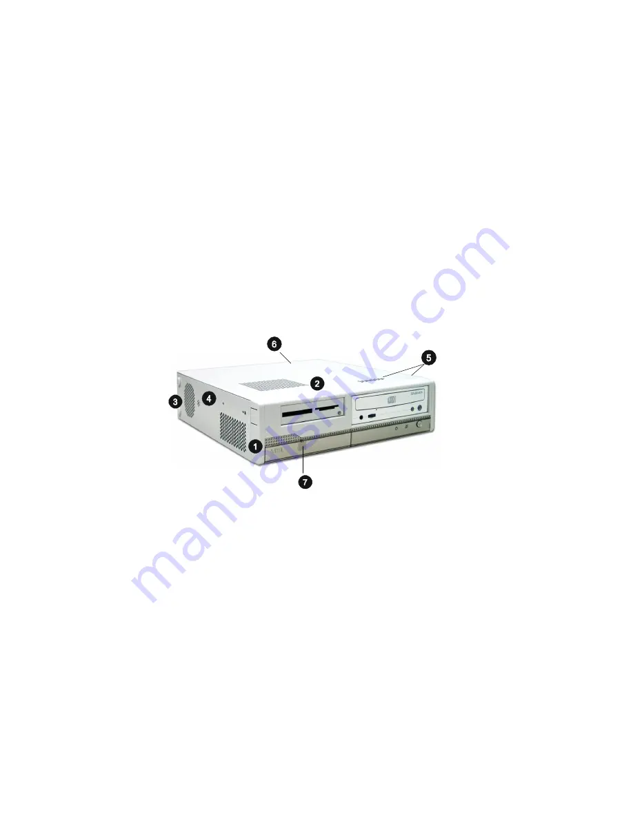
 Multiple ventilation holes

1.  CPU Fan Ventilation Hole

5.  System Ventilation Holes

2.  CPU Fan Ventilation Hole

6.  Power Supply Ventilation Hole

3.  System Fan Ventilation Hole

7.  Front I/O Release Button

4.  Built-in Speaker

Summary of Contents for 865GV-E - Hetis - Lite

Page 1: ...User s Guide Hetis 865GV E G52 B6279X1 ...

Page 2: ...ial area is likely to cause harmful interference in which case the user will be required to correct the interference at his own expense Notice 1 The changes or modifications not expressly approved by the party responsible for compliance could void the user s authority to operate the equipment Notice 2 Shielded interface cables and AC power cord if any must be used in order to comply with the emiss...

Page 3: ...ovision Corporation and is intended for home and other limited viewing users only unless otherwise authorized by Macrovision Corporation Reverse engineer ing or disassembly is prohibited Copyright Notice The material in this document is the intellectual property of MICRO STAR INTERNATIONAL We take every care in the preparation of this document but no guarantee is given as to the correctness of its...

Page 4: ...marks of International Business Machines Corporation Windows 95 98 2000 NT XP are registered trademarks of Microsoft Corporation Netware is a registered trademark of Novell Inc Award is a registered trademark of Phoenix Technologies Ltd AMI is a registered trademark of American Megatrends Inc Revision History Revision Revision History Date V1 0 First Release September 2004 ...

Page 5: ... CPU 2 3 2 3 Memory 2 3 Memory Speed CPU FSB Support Matrix 2 3 DDR Population Rules 2 4 DDR Module Combination 2 4 Installing DDR Modules 2 5 2 4 Power Supply 2 6 2 5 Front Panel 2 7 SPDIF Out Jack 2 7 Audio Ports 2 7 USB Ports 2 8 IEEE 1394 Port J1394 2 2 8 2 6 Rear Panel 2 9 Mouse Keyboard Connectors 2 9 Audio Ports 2 10 Composite Connector TV1 2 10 RJ45 LAN Jack 2 11 USB Ports 2 11 Parallel Po...

Page 6: ... 19 2 8 Jumpers 2 20 Clear CMOS Jumper JBAT1 2 20 2 9 Slots 2 21 PCI Interrupt Request Routing 2 21 Chapter 3 System Assembly 3 1 3 1 Overview 3 2 3 2 Installation Procedures 3 4 1 Removing Cover Front Bezel Drives Cage and HDD tray 3 4 2 Installing Memory Modules 3 7 3 Installing CPU 3 8 4 Releasing Coolor Clips 3 9 5 Installing CPU Cooler 3 10 6 Installing HDD 3 12 7 Installing Optical Drive and...

Page 7: ...agement Features 4 14 4 7 PNP PCI Configurations 4 18 4 8 Integrated Peripherals 4 21 4 9 PC Health Status 4 26 4 10 Frequency Voltage Control 4 27 4 11 Set Supervisor User Password 4 29 4 12 Load Optimal Fail Safe Defaults 4 30 Chapter 5 Using 4 or 6 Channel Audio Function 5 1 5 1 Installing the Audio Drivers 5 2 5 2 Using Audio Function 5 4 5 3 Testing the Connected Speakers 5 8 5 4 Playing Kara...

Page 8: ...y add on card or module 9 All cautions and warnings on the equipment should be noted 10 Never pour any liquid into the opening that could damage or cause electrical shock 11 If any of the following situations arises get the equipment checked by a service personnel The power cord or plug is damaged Liquid has penetrated into the equipment The equipment has been exposed to moisture The equipment has...

Page 9: ...one is your best Slim PC choice Based on the all in one design idea Hetis provides USB ports and optional TV out jack DVI jack and 1394 ports With the fantastic appear ance and small form factor it can easily be set anywhere The feature packed platform also gives you an exciting PC experience ...

Page 10: ... SupportsDDR 400 333 266 memory interface Intel ICH5 chipset Hi Speed USB USB2 0 controller 480Mb sec 8 ports 2 SerialATA 150 ports 2 channel Ultra ATA 100 bus Master IDE controller PCI Master v2 3 I OAPIC Supports both ACPI and legacy APM power management MainMemory Two 184 pin DDRDIMM slots Supports dual channelDDR 400 333 266 memory up to 2GB For the updated supporting memory modules please vis...

Page 11: ...J45 LAN Jack x1 IEEE1394 6 pins x 1 optional Internal I O IDE 2x20 x1 CDAudio Input 1x4 x 1 Internal Speaker Header x 1 I2 C Connector x 1 Internal USB Connector 1x10 x 1 Audio AC 97 link controller integrated in ICH5 RealtekALC655 6 channel audio AC 97 v2 3 compliance Onboard Amplifier AnalogDevice SSM2211S LAN 10 100 1000 Controller Realtek 8110S IEEE1394 VIA6307 2 ports On BoardGraphics Integra...

Page 12: ... Front View 1 Power Switch 6 4 pin IEEE 1394 Port optional 2 Power LED 7 4 x USB 2 0 Ports 3 HDD LED 8 Mic in pink Line out green 4 Optical Drive optional 9 SPDIF out 5 Card Reader optional 1 2 System Configuration ...

Page 13: ...deo out optional 3 Line out 12 Serial Ports 4 AV out optional 13 Parallel Port 5 DVI Port optional 14 PCI Slots 6 VGA Port 15 RJ 45 LAN Jack 7 2 x USB 2 0 Ports 16 PS 2 Mouse 8 PS 2 Keyboard 17 Voltage Selector 115 230V 9 6 pin IEEE 1394 Port optional 18 Ventilation Hole ...

Page 14: ... Minimized screw structure Detachable bay housing Multiple ventilation holes 1 CPU Fan Ventilation Hole 5 System Ventilation Holes 2 CPU Fan Ventilation Hole 6 Power Supply Ventilation Hole 3 System Fan Ventilation Hole 7 Front I O Release Button 4 Built in Speaker ...

Page 15: ...tiple ventilation holes for better cooling effects The specially designed CPU cooler supports Intel Northwood FSB 800 CPU up to 3 0GHz and Prescott up to 3 4GHz and above The following figures illustrate how the system fan effectively exhausts hot air through multiple ventilation holes CPU Fan Air Flow Direction CPU Fan Air In Air Out ...

Page 16: ...Chapter 1 1 8 Power Supply Power Supply Fan Ventilation Hole System Fan Ventilation Hole Ventilation Hole CPU Fan Ventilation Hole front panel ...

Page 17: ... Flow Direction After the installation is completed please keep other objects away from the ventilation hole at least 2 5cm and above Do not block the ventila tion hole System Fan CPU Cooler Power Supply Power Supply Fan front panel ...

Page 18: ...s well as how to setup the jumpers on the mainboard Also it provides the instructions on connecting the peripheal devices such as the mouse keyboard etc While doing the installation be careful in holding the compo nents and follow the installation procedures Introducing Mainboard ...

Page 19: ...dec IDE1 SATA2 SATA1 JPW1 CPU FAN1 SYS _FAN1 JFP1 Top m ouse Bottom key board Top LAN Jack B ot tom USB ports J 1394 2 Intel 865GV chipset ICH 5 1394 port To p P arallel P ort Bottom VGA DV I I connecto r option al TV1 TOP COM1 Bot tom green Line out blue Line in pink Mic in 1394 po rt pink MI C in green Line Out U SB por ts U SB por ts S PDIF DDR1 DDR2 CON1 JTV1 ...

Page 20: ...ge the CPU and system always make sure the cooling fan can work properly to protect the CPU from overheating 3 While replacing the CPU always turn off the ATX power supply or unplug the power supply s power cord from grounded outlet first to ensure the safety of CPU The mainboard provides two sockets for 184 pin DDR SDRAM DIMM Double In Line Memory Module and supports the memory size up to 2 GB Yo...

Page 21: ...GB DDR Module Combination DDR Population Rules Install at least one DIMM module on the slots Each DIMM slot supports up to a maximum size of 1GB Users can install either single or double sided modules to meet their own needs Please note that each DIMM can work respectively for single channel DDR but there are some rules while using dual channel DDR Please refer to the suggested DDR population tabl...

Page 22: ... on the center of module The module will only fit in the right orientation 2 Insert the DIMM memory module vertically into the DIMM slot Then push it in 3 The plastic clip at each side of the DIMM slot will automatically close Volt notch Installing DDR Modules ...

Page 23: ...ctor supports instant power on function which means that system will boot up immediately when the power supply connector is inserted on the board ATX 12V Power Connector JPW1 This 12V power connector is used to provide power to the CPU 2 4 Power Supply JPW1 1 3 2 4 ATX1 10 1 20 11 PIN SIGNAL 1 GND 2 GND 3 12V 4 12V JPW1 Pin Definition PIN SIGNAL 11 3 3V 12 12V 13 GND 14 PS_ON 15 GND 16 GND 17 GND ...

Page 24: ...connect to Sony Philips Digital Inter face SPDIF developed jointly by the Sony and Philips corporations A standard audio file transfer format SPDIF allows the transfer of digital audio signals from one device to another without having to be converted first to an analog format Mini IEEE 1394 Port J1394 2 USB Ports Audio Ports Optical SPDIF Out MIC in Line out ...

Page 25: ...IEEE 1394 high speed serial bus complements USB by providing enhanced PC connectivity for a wide range of devices including consumer electronics audio video A V appliances storage peripherals other PCs and portable devices Software Support IEEE 1394 Driver is provided by Windows 98 SE Windows XP Windows ME and Windows 2000 Just plug in the IEEE 1394 connector into the port These Operating Systems ...

Page 26: ...3 4 5 6 PS 2 Mouse 6 pin Female MIC in Line in Line out TV1 DVI Port VGA Port USB Ports Keyboard J1394 1 COM Parallel Port LAN Jack Mouse PIN SIGNAL DESCRIPTION 1 Mouse DATA Mouse DATA 2 NC No connection 3 GND Ground 4 VCC 5V 5 Mouse Clock Mouse clock 6 NC No connection Mouse Pin Definition PIN SIGNAL DESCRIPTION 1 Keyboard DATA Keyboard DATA 2 NC No connection 3 GND Ground 4 VCC 5V 5 Keyboard Clo...

Page 27: ...onnector for Speakers or Headphones Line In is used for external CD player Tape player or other audio devices MIC is a connector for stereo microphones Composite Connector TV1 You can connect a TV or video device to TV1 connector for video out function which allows you to output the image to a TV or video device 1 8 Stereo Audio Connectors Line Out Line In MIC ...

Page 28: ... devices You can plug the USB device directly into the connector The mainboard supports USB1 1 2 0 devices PIN SIGNAL DESCRIPTION 1 VCC 5V 2 Data 0 Negative Data Channel 0 3 Data0 Positive Data Channel 0 4 GND Ground 5 VCC 5V 6 Data 1 Negative Data Channel 1 7 Data 1 Positive Data Channel 1 8 GND Ground USB Port Description RJ45 LAN Jack USB Ports 1 2 3 4 5 6 7 8 Giga bit LAN Pin Definition PIN SI...

Page 29: ...T Select 14 AUTO FEED Automatic Feed 15 ERR Error 16 INIT Initialize Printer 17 SLIN Select In 18 GND Ground 19 GND Ground 20 GND Ground 21 GND Ground 22 GND Ground 23 GND Ground 24 GND Ground 25 GND Ground Pin Definition Parallel Port The mainboard provides a 25 pin female centronic connector as LPT A parallel port is a standard printer port that supports Enhanced Parallel Port EPP and Extended C...

Page 30: ...cs data sent to the digital monitor use Transition Minimized Differential Signalling T M D S technology TMDS uses an encoding algorithm to 8 bit of data into a 10 bit transition minimized DC balanced character which are transition minimized to reduce EMI with copper cables and DC balanced for transmission over fiber optic cables The TMDS algorithm also provides robust clock recovery for greater sk...

Page 31: ...pin female connector to connect a VGAmonitor Software Support IEEE 1394 Driver is provided by Windows 98 SE Windows XP Windows ME and Windows 2000 Just plug in the IEEE 1394 connector into the port These Operating Systems will install the driver for IEEE 1394 VGA Port Pin Definition PIN SIGNAL DESCRIPTION 1 Red 2 Green 3 Blue 4 Not used 5 Ground 6 Ground 7 Ground 8 Ground 9 Power 10 Ground 11 Not ...

Page 32: ...ch a serial mouse or other serial devices directly to the connector Serial Port PIN SIGNAL DESCRIPTION 1 DCD Data Carry Detect 2 SIN Serial In or Receive Data 3 SOUT Serial Out or Transmit Data 4 DTR Data Terminal Ready 5 GND Ground 6 DSR DataSetReady 7 RTS Request To Send 8 CTS ClearTo Send 9 RI Ring Indicate Serial Port Pin Definition 9 Pin Male DIN Connector 1 2 3 4 5 6 7 8 9 1 2 COM2 9 ...

Page 33: ...tors SATA1 SATA2 The southbridge of this mainboard is ICH5 which supports two serial connectors SATA1 SATA2 SATA1 SATA2 are dual high speed Serial ATA interface ports Each supports 1st generation serial ATA data rates of 150 MB s Both connectors are fully compliant with Serial ATA 1 0 specifications The Serial ATA connector allows you to connect the hard disk device of Serial ATA interface IDE1 SA...

Page 34: ...wn to GND 6 PWR_SW_P Power Switch high reference pull up 7 RST_SW_P Reset Switch high reference pull up 8 PWR_SW_N Power Switch low reference pull down to GND 9 RSVD_DNU Reserved Donot use JFP1 Pin Definition Front Panel Connector JFP1 The mainboard provides one front panel connector for you to connect to the front panel switches and LEDs JFP1 is compliant with Intel Front Panel I O Connectivity D...

Page 35: ...e is the positive and should be connected to the 12V that is controlled by PWM the black wire is Ground and should be connected to GND If the mainboard has a System Hardware Monitor chipset on board you must use a specially designed fan with speed sensor to take advantage of the CPU fan control Fan Power Connectors CPUFAN1 SYS_FAN1 On Board S Video out Connector JTV1 The mainboard provides a TV ou...

Page 36: ...SB 2 0 technology increases data transfer rate up to a maximum throughput of 480Mbps which is 40 times faster than USB 1 1 PIN SIGNAL PIN SIGNAL 1 VCC 2 VCC 3 USB0 4 USB1 5 USB0 6 USB1 7 GND 8 GND 9 Key no pin 10 USBOC J3 Pin Definition J3 1 2 10 9 Note that the pins of VCC and GND must be connected correctly or it may cause some damage ...

Page 37: ...onfiguration data With the CMOS RAM the system can automatically boot OS every time it is turned on That battery has long life time for at least 5 years If you want to clear the system configuration use the JBAT1 Clear CMOS Jumper to clear data Follow the instructions below to clear the data You can clear CMOS by shorting 2 3 pin while the system is off Then return to 1 2 pin position Avoid cleari...

Page 38: ...o the PCI bus INT A INT D pins as follows The mainboard provides one 32 bit Master PCI bus slot The PCI slot allows you to insert PCI Riser Card The PCI Riser Card is included in the barebone The Riser Card allows you to insert two expansion cards You can insert any type of PCI cards to meet your needs When adding or removing expansion cards make sure that you unplug the power supply first Meanwhi...

Page 39: ... Assembly 3 1 This chapter provides you with the installation procedures of Hetis barebone It is useful for you to read the information of mainboard setup before assembling the whole system 3 System Assembly ...

Page 40: ...of screws are used in assembling the barebone round headed screw hexagonal screw with washer thumb screw and flat headed screw Round headed screw This type of screw is used to attach the HDD to the HDD tray Hexagonal screw with washer The screw is used to fasten the optical drive to the drives cage Round headed screw This type of screw is used to fasten the card reader to the drives cage Thumb scr...

Page 41: ...ems Before assembling your system please check the items listed below for basic system operation You may install a card reader to enhance your system perofrmance CPU Cooler Footstand IDE or SATA HDD Optical Drive Card Reader optional CPU ...

Page 42: ...ver Remove the chassis cover Use a screw driver to unscrew the drives cage 1 Removing Cover Front Bezel Drives Cage and HDD tray 3 2 Installation Procedures Press the locking tabs simultaneously to release the front bezel from the chassis ...

Page 43: ...Remove the front bezel Press the lock brackets inwards and then pull the drives cage forwards to remove it from the chassis Remember to unplug the power cord while removing the drives cage The drives cage has been removed ...

Page 44: ...Chapter 3 3 6 The HDD tray has been removed Pull the HDD tray forwards to remove from the chassis Push the tray lever to release the tray Pull the lever in the direction indicated to take out the tray ...

Page 45: ...tically into the slot Note The DIMM has only one notch on the center of module It will only fit in the right direction The plastic clip at each side of the DIMM slot will automatically close 2 Installing Memory Modules Locate the DIMM slots ...

Page 46: ...way from the socket and raise it up to 90 degree angle Close the lever to complete the installaton 3 Installing CPU Put the CPU onto the socket Note Make sure the pins are completely embedded into the socket The CPU can only fit in the correct direction ...

Page 47: ... If the metal clip is closed push the black tab to open the clip Remember to do so on four clips Before installing the CPU cooler check to see if the four metal clips of the CPU cooler are closed 4 Releasing Cooler Clips ...

Page 48: ...he CPU cooler onto the CPU socket 5 Installing CPU Cooler Close the lever to secure the CPU cooler Please note that the metal clips must not be placed inside the CPU cooler rack Instead they should be placed outside the rack ...

Page 49: ...System Assembly 3 11 Connect the power cord of the CPU cooler ...

Page 50: ...apter 3 3 12 6 Installing HDD Use 4 screws to secure the IDE HDD module Insert the IDE HDD module into the tray Note The systemsupports bothIDE and SATAinterfaced HDD Connect the HDD cable and power cord ...

Page 51: ...3 13 Insert the HDD tray into the chassis and close the lever to lock the HDD tray in place Using SATAHDD Here shows how the cables should be connected to the SATA HDD Connect the SATAcable HDD power cord and HDD cable ...

Page 52: ...Chapter 3 3 14 7 Installing Optical Drive and Card Reader Insert the optical drive into the drives cage Screw the optical drive to Position I Use 4 screws to secure the optical drive ...

Page 53: ...System Assembly 3 15 Slide the drives cage back into the chassis Connect the optical drive cable and power cord Connect the system power cord Screw the drives cage to the chassis ...

Page 54: ... 16 Replace the front bezel Unscrew the cover shield Take out the cover shield Take out the shield marked if an optical drive is installed Take out both shields if an optical drive and a card reader are installed ...

Page 55: ...System Assembly 3 17 Press with force to secure the front bezel to the chassis ...

Page 56: ...reader from the rear into the drives cage Screw the card reader to the drives cage following the indicated order Note Card readeris an optional device If you do not intend to install a card reader please skip the following procedures ...

Page 57: ...ssembly 3 19 Slide the drives cage back into the chassis Screw the drives cage to the chassis and replace the front bezel Unscrew the cover shield and then take it out Connect the power cord of the card reader ...

Page 58: ...Chapter 3 3 20 Remember to fasten the screws on the rear panel 8 Replacing Chassis Cover Replace the chassis cover Put the barebone on the footstand ...

Page 59: ...OS Setup pro gram and allows you to configure the system for optimum use You may need to run the Setup program when An error message appears on the screen during the system m booting up and requests you to run SETUP You want to change the default settings for customized features ...

Page 60: ...hen the same message as listed above appears on the screen press F11 to trigger the boot menu The POST messages might pass by too quickly for you to respond in time If so restart the system and press F11 after around 2 or 3 seconds to activate the boot menu similar to the following The boot menu will list all the bootable devices Select the one you want to boot from by using arrow keys and then pr...

Page 61: ...e BIOS Setup and High Performance defaults BIOS Setup defaults provide stable performance settings for all devices and the system while High Performance defaults provide the best system performance but may affect the system stability Move to the previous item Move to the next item Move to the item in the left hand Move to the item in the right hand Enter Select the item Esc Exit menu or returns to...

Page 62: ...pset registers and optimize your system s performance Power Management Features Use this menu to specify your settings for power management PNP PCI Configurations This entry appears if your system supports PnP PCI Once you enter AMIBIOS NEW SETUP UTILITY the Main Menu will appear on the screen The Main Menu displays twelve configurable functions and two exit choices Use arrow keys to move among th...

Page 63: ...sword Use this menu to set Supervisor Password Set User Password Use this menu to set User Password Load Optimal Defaults Use this menu to load the default values set by the mainboard manufacturer specifically for optimal performance of the mainboard Load Fail Safe Defaults Use this menu to load the default values set by the BIOS vendor for stable system performance Save Exit Setup Save changes to...

Page 64: ...his allows you to set the system time that you want usually the current time The time format is hour minute second SystemDate This allows you to set the system to the date that you want usually the current date The format is day month date year day Day of the week from Sun to Sat determined by BIOS Read only month The month from Jan through Dec date The date from 1 to 31 can be keyed by numeric fu...

Page 65: ... Enter head number Write Precompensation Enter write precomp cylinder Sectors Enter sector number Maximum Capacity Read the maximal HDD capacity LBAMode Select Auto for a hard disk 512 MB un der Windows and DOS or Disabled un der Netware and UNIX Block Mode Select Auto to enhance the hard disk performance Fast Programmed I O Select Auto to enhance hard disk perfor Modes mance by optimizing the har...

Page 66: ...e it will skip some check items Available options Enabled Disabled BootDevice Select Press Enter to enter the sub menu screen BootDevice Priority 1st 2nd 3rd The items allow you to set the sequence of boot devices where BIOS attempts to load the operating system 4 4 Advanced BIOS Features ...

Page 67: ...going to fail to a safe place before the hard disk becomes offline Settings Enabled Disabled BootUpNum Lock This item is to set the Num Lock status when the system is powered on Setting to On will turn on the Num Lock key when the system is powered on Setting to Off will allow end users to use the arrow keys on the numeric keypad Setting options On Off Password Check This specifies the type of AMI...

Page 68: ... the system is able to run inAPIC mode EnablingAPIC mode will expand available IRQs resources for the system Settings Enabled and Disabled CPU L1 L2 Cache Cache memory is additional memory that is much faster than conventional DRAM system memory When the CPU requests data the system transfers the requested data from the main DRAM into cache memory for even faster access by the CPU The setting cont...

Page 69: ...ns Enabled Disabled C000 32k Shadow This item specifies how the contents of the adapter ROM named in the item are handled Settings are described below Option Description Disabled The specified ROM is not copied to RAM Enabled The contents of specified ROM are copied to RAM for faster system performance Cached The contents of specified ROM are not only copied to RAM the contents of the ROM area can...

Page 70: ...by the SPD Serial Presence Detect EEPROM on theDRAM module Setting to Enabled enables the following fields automatically to be determined by BIOS based on the configurations on the SPD Selecting Disabled allows users to config ure these fields manually 4 5 Advanced Chipset Features NOTE Change these settings only if you are familiar with the chipset ...

Page 71: ...g of the transition from RAS row address strobe to CAS column address strobe The less the clock cycles the faster the DRAM performance Setting options 2 clocks 3 clocks 4 clocks Precharge Delay This setting controls the precharge delay which determines the timing delay for DRAM precharge Settings 5 clocks 6 clocks 7 clocks 8 clocks Burst Length This setting allows you to set the size of Burst Leng...

Page 72: ...ons are S1 POS The S1 sleep mode is a low power state In this state no system context is lost CPU or chipset and hardware maintains all system context S3 STR The S3 sleep mode is a lower power state where the information of system configuration and open applications files is saved to main memory that remains powered while most other hardware components turn off to save energy The information store...

Page 73: ...te After the selected period of system inactivity all devices except the CPU shut off Settings Disabled 1 2 4 8 10 20 30 40 50 60 Power ButtonFunction This feature sets the function of the power button Settings are On Off The power button functions as normal power off button Suspend When you press the power button the computer enters the suspend sleep mode but if the button is pressed for more tha...

Page 74: ... the USB devices keyboard and mouse to wake up the system from S3 sleep state Setting Enabled Disabled Keyboard Wake up From S3 You have two options Any Key Disabled Selecting Any Key allows you to power on the system by pressing any key Mouse Wake up From S3 Selecting Enabled allows you to power on the system by clicking the mouse Setting Enabled Disabled Resume on Ring You need to install a mode...

Page 75: ...ower off S5 state Settings Enabled Disabled RTCAlarmDate Hour Minute Second If Resume On RTC Alarm is set to Enabled the system will automatically resume boot up on a specific date hour minute second specified in these fields Available settings for each item are AlarmDate 01 31 Every Day Alarm Hour 00 23 Alarm Minute 00 59 Alarm Second 00 59 ...

Page 76: ...NVRAM Nonvolatile Ran dom Access Memory is where the BIOS stores resource information for both PNP and non PNP devices in a bit string format When the item is set to Yes the system will reset ESCD NVRAM right after the system is booted up and then set the setting of the item back to No automatically PCI LatencyTimer PCI Clocks This item controls how long each PCI device can hold the bus before ano...

Page 77: ...s BIOS to automatically deter mine the IRQ line for each PCI slot Set IRQs to PCI orISA Press Enter to enter the sub menu and the following screen appears IRQ 3 4 5 7 9 10 11 14 15 These items specify the bus where the specified IRQ line is used The settings determine if BIOS should remove an IRQ from the pool of available IRQs passed to devices that are configurable by the system BIOS The availab...

Page 78: ...t the system DMA Direct MemoryAccess channel is used The settings determine if BIOS should remove a DMA from the available DMAs passed to devices that are configurable by the system BIOS The available DMApool is determined by reading the ESCDNVRAM If more DMAs must be removed from the pool the end user can reserve the DMA by assigning a ISA EISA setting to it ...

Page 79: ...t Set to Enabled if your need to use any USB 1 1 2 0 device in the operating system that does not support or have any USB 1 1 2 0 driver installed such as DOS and SCO Unix Setting options Disabled Enabled On ChipIDEConfiguration Press Enter to enter the sub menu and the following screen appears 4 8 Integrated Peripherals ...

Page 80: ...mode Non Combined Mode P ATA devices only Maximum of 4 devices Non Combined Mode S ATA devices only Maximum of 2 devices Combined Mode S ATA devices P ATA devices Maximum of 2 devices each thus total 4 devices at maximum Native Mode In this mode system BIOS will search all available IRQs to use for HDD New OS that support switch to Native Mode WinXP Windows NET Server can set SATA and PATA to Nati...

Page 81: ... S ATAPorts Definition This allows you to set the boot sequence of serial ATA ports Onboard LAN 1394 This item is used to enable disable the onboard LAN 1394 controllers Setting Enabled Disabled AC97Audio Auto allows the motherboard s BIOS to detect whether you re using any audio device If so the onboard audio controller will be enabled If not the onboard audio controller will be disabled If you w...

Page 82: ... options Full Duplex Half Duplex Under Full Duplex mode synchronous bi directional transmission reception is allowed Under Half Duplex mode only asynchronous bi directional transmission reception is allowed IR Receiver Xmitter Polarity This setting controls the data transfer speed of IR transmission reception Setting options High Low Onboard Parallel Port This field specifies the base I O port add...

Page 83: ...IOS determines the IRQ for the parallel port automatically Parallel Port DMAChannel This feature needs to be configured only when Parallel Port Mode is set to the ECP mode When Parallel Port is set to Auto the field will show Auto indicating that BIOS automatically determines the DMA channel for the parallel port ...

Page 84: ...ly return to Enabled later Settings Enabled Reset Disabled Smart FanControl Function This field enables or disables smart fan control function If you choose enable CPU fan and system fan speed will depend on CPU temperature When CPU temperature is high the fan will spin quickly This function will reduce the noise produced by fan If you disable it the CPU fan and system fan will spin in full speed ...

Page 85: ...ngs are PSB 400 266 Auto PSB 533 266 333 Auto PSB 800 266 333 400 Auto Spread Spectrum When the motherboard s clock generator pulses the extreme values spikes of the pulses creates EMI Electromagnetic Interference The Spread Spectrum function reduces the EMI generated by modulating the pulses so that the spikes of the pulses are reduced to flatter curves If you do not have any EMI problem leave th...

Page 86: ...er can introduce a temporary boost in clockspeed which may just cause your overclocked processor to lock up CPU FSB Clock MHz This item shows the CPU FSB Front Side Bus information It doesn t allow you to make any setting DDR Clock MHz This item shows the DDR clock speed It doesn t allow you to make any setting ...

Page 87: ...t you will be prompted to enter it every time you try to enter Setup This prevents an unauthorized person from changing any part of your system configuration Additionally when a password is enabled you can also have AMIBIOS to request a password each time the system is booted This would prevent unauthorized use of your computer The setting to determine when the password prompt is required is the P...

Page 88: ...e Fail Safe Defaults are the default values set by the mainboard manufacturer for stable performance of the mainboard When you select Load Optimal Defaults a message as below appears Pressing Enter loads the default values that are factory settings for stable system performance When you select Fail Safe Defaults a message as below appears Pressing Enter loads the default BIOS values that enable th...

Page 89: ...5 chip which provides support for 6 channel audio output including 2 Front 2 Rear 1 Center and 1 Subwoofer channel ALC655 allows the board to attach 4 or 6 speakers for better surround sound effect The section will tell you how to install and use 4 6 channel audio function on the board ...

Page 90: ...e driver The following illustrations are based on Windows XP environment and could look slightly different if you install the drivers in different operating systems 1 Insert the companion CD into the CD ROM drive The setup screen will automatically appear 2 Click RealtekAC97 Audio Drivers 5 1 Installing the Audio Drivers The AC97 Audio Configuration software utility is under continuous update to e...

Page 91: ...5 3 Using Audio Function 3 Click Next to start installing files into the system 4 Click Finish to restart the system Select this option ...

Page 92: ...er of the screen 2 Select a desired surround sound effect from the Environment drop down menu 3 Click the Speaker Configuration tab 4 Select Synchronize the phonejack switch with the speaker setting 5 Select a desired multi channel operation from Number of Speakers a Headphone b 2 Channel Mode for Stereo Speaker Output c 4 Channel Mode for 4 Speaker Output d 6 Channel Mode for 5 1 Speaker Output 6...

Page 93: ...5 5 Using Audio Function 2 3 4 5 6 ...

Page 94: ...e Out Front channels Back Panel 3 1 2 1 MIC 2 Line Out Rear channels 3 Line Out Front channels Line In function is converted to Line Out function when 4 Channel Mode for 4 Speaker Output is selected n 4 Channel Mode for 4 Speaker Output The audio jacks on the back panel always provide 2 channel analog audio output function however these audio jacks can be transformed to 4 or 6 channel analog audio...

Page 95: ...put is selected n 6 Channel Mode for 6 Speaker Output Refer to the following diagram and caption for the function of each jack on the back panel when 6 Channel Mode is selected Back Panel If the Center and Subwoofer speaker exchange their audio channels when you play video or music on the computer a converter may be required to exchange center and subwoofer audio signals You can purchase the conve...

Page 96: ... ones Testing Each Speaker 1 Click the audio icon from the window tray at the lower right corner of the screen 2 Click the Speaker Test tab 3 The following window appears Select the speaker which you want to test by clicking it Subwoofer Front Right Rear Right Center Front Left Rear Left 5 3 Testing the Connected Speakers 6 speakers appear on the Speaker Test window only when you select 6 Channel ...

Page 97: ...w in bright color 5 While you are testing the speakers in 6 Channel Mode if the sound coming from the center speaker and subwoofer is swapped you should select Swap Center Subwoofer Output to readjust these two channels Select this function tested speaker ...

Page 98: ...u to sing the song Note that this function applies only for 2 channel audio operation Playing KaraOK 1 Click the audio icon from the window tray at the lower right corner of the screen 2 In the Sound Effect tab select Voice Cancellation under KaraOK 3 Click OK to close this window 2 3 5 4 Playing KaraOK ...

Reviews: