


English
Operation manual
31
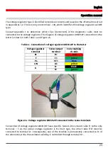
4. Connect a “GC” clip (yellow) t
o the LIN bus wire using a flexible probe pin. The tester will start
reading data.
5. To stop data reading, disconnect the “GC” clip from the bus.
6. Push “REC” to save data to the device storage. Once the data have been read, push “Save”,
name the file,
and push “Ok”.
7. To view the saved data, connect the tester to a computer and upload the file you saved from
the “Trace” folder in the tester storage.
6.2. Bomber Mode
Bomber Mode is intended to identify PID of the units controlled via a LIN bus.
WARNING!
Do not connect the tested unit to a Master module.
The procedure for PID identification is as follows:
1. Connect cable MS-33501 to the tester and supply power to the device.
2. Supply power to the tested unit.
3. In the menu on the device
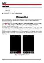
screen select “LIN Analyzer”, then “Bomber” and set a LIN bus speed
(Fig. 25). Once you push “OK”, the test mode window will appear (Fig. 28).
Figure 28 Bomber Mode Screen
4. Connect a “GC” clip (yellow) to the LIN bus wire and push “RUN”.
5. After data reading is completed, the response data will be displayed on the screen.
Summary of Contents for MS016
Page 2: ......
Page 105: ...MS016 105 ...
Page 106: ...MS016 106 ...
Page 108: ...MS016 108 ...
Page 109: ...MS016 109 ...
Page 110: ...MS016 110 ...
Page 111: ...MS016 111 ...
Page 112: ...MS016 112 ...
Page 113: ...MS016 113 ...
Page 114: ...MS016 114 ...
Page 115: ...NOTES 115 ...
Page 116: ......


